Ford C6 Valve Body Diagram and Component Identification
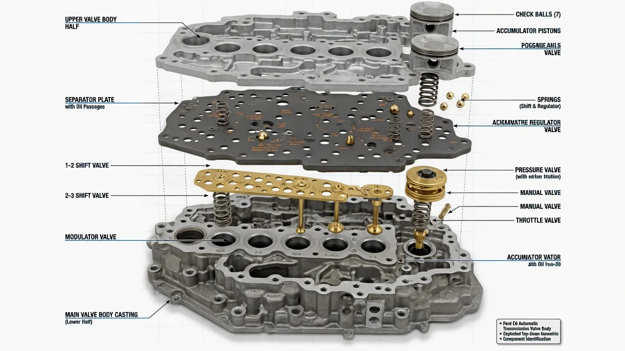
The valve body is the hydraulic control center of the Ford C6, the heavy-duty three-speed automatic used for roughly three decades in Ford trucks, vans and large cars. A good diagram helps you identify its castings, valves, springs and check balls, but only if it matches your unit. This guide explains what the diagram shows, how the parts work together and what to confirm before you buy parts or take the assembly apart.
What a C6 Valve Body Diagram Shows
The C6 valve body bolts to the bottom of the case, above the filter screen and oil pan. A typical exploded diagram shows stacked castings separated by a steel separator plate and gaskets, with spool valves, springs, retainers and plugs fitted into machined bores. The separator plate has sized holes that meter oil between passages, and small check balls sit in pockets in the casting, where they open or close specific circuits depending on which side has pressure. Most diagrams also show the filter screen mounting points and how the manual valve connects to the shift lever inside the case.
The parts you will usually be asked to identify are the manual valve, which the gear selector moves; the 1-2 and 2-3 shift valves; the pressure regulating valves that set line pressure; the downshift valve operated by the kickdown linkage; throttle-related valves that respond to the vacuum modulator signal; and timing or accumulator-related valves that cushion clutch and band engagement. Valve names, spring counts and check ball positions vary between factory service literature, rebuild manuals and aftermarket kit instructions, so use the diagram as a map of functions and then confirm details against your actual parts.
How the Valve Body Controls Shifts
The front pump supplies fluid whenever the engine runs, and the regulating valves turn that flow into controlled line pressure. The manual valve then routes oil according to the selector position, feeding only the circuits allowed in that range. The C6 makes its shift decisions hydraulically rather than electronically, which is why it has no shift solenoids or transmission control module.
Each shift valve works as a balance between two signals. Governor pressure, produced by the governor on the output shaft, rises with road speed and pushes the valve toward an upshift. Throttle pressure, controlled by the vacuum modulator on the case, rises as engine vacuum drops under load and pushes against the upshift, which is why shifts happen later when you accelerate harder. When governor pressure wins, the valve moves and sends oil to the next apply element. At wide throttle, the kickdown linkage moves the downshift valve to force a lower gear, within the limits set by road speed. Accumulators and the restrictions in the separator plate control how quickly each element applies, which largely determines shift feel.
Knowing what each gear applies makes a diagram easier to trace. The C6 uses a forward clutch, a reverse-high clutch, a low-reverse clutch and a single intermediate band. First gear uses the forward clutch with a one-way clutch holding in Drive, and the low-reverse clutch adds engine braking in manual low. Second uses the forward clutch and intermediate band, third uses the forward and reverse-high clutches, and reverse uses the reverse-high and low-reverse clutches.
What Changes the Diagram for Your Transmission
Ford built the C6 over a long production run and for many applications, including gasoline and diesel trucks, vans and full-size passenger cars. Valve body castings, separator plates, springs and calibrations changed over time and by application, so a diagram for one year or model may not match another. A plate with different hole sizing or a casting with different check ball pockets can change shift timing and firmness even when the parts look nearly identical. The factory fluid specification also changed during production, so confirm it for your vehicle rather than assuming one fluid suits every C6.
Modifications change the picture as well. Shift kits commonly replace springs, alter plate holes or remove check balls, and manual or reverse-pattern valve bodies used in performance applications eliminate automatic upshifts entirely. A previous owner may also have installed a transmission from another vehicle. Correct fitment depends on matching the casting, separator plate, gaskets and linkage, not just the transmission type name. If the service history is unknown, assume the internals may differ from any factory drawing until you have inspected them.
What Owners Can Check First
Start by confirming the transmission type. The C6 is commonly recognized by its 17-bolt oil pan and the vacuum modulator on the case, and many units still carry an identification tag with the model code used for parts lookup. Record the vehicle year, engine and tag information before ordering a valve body, rebuild kit or gasket set.
Symptoms such as late or harsh shifts, a missing 2-3 upshift, slipping or no kickdown can involve the valve body, but they do not confirm it. Low or degraded fluid, a leaking modulator diaphragm, misadjusted kickdown or shift linkage, a sticking governor, an out-of-adjustment intermediate band or worn clutches can produce similar shift behavior. Check fluid level and condition using the procedure for your vehicle, look for transmission fluid in the modulator vacuum hose, and verify linkage adjustment. Because the C6 has no electronic shift control, there are no transmission diagnostic codes to read, although engine problems that affect vacuum can still influence shifting. A line pressure test with a gauge is the usual way to separate pressure-control faults from mechanical wear.
If You Remove the Valve Body
If diagnosis points to the valve body, work slowly and document everything. Drain the fluid, remove the pan and filter screen, and note how the manual valve and kickdown parts engage before lowering the assembly. Photograph each side before separating the castings, because check balls can fall out and their pockets are easy to confuse. Keep each valve, spring and plug in order on a clean surface, and compare springs side by side rather than relying on memory.
Clean parts with solvent and lint-free cloths, then confirm that each clean, lubricated valve slides freely in its bore. Look for scoring, burrs, debris in passages and damage to the separator plate. Do not force a stuck valve or polish bores aggressively, since the clearances are small. Use new gaskets that match your plate, and tighten the valve body bolts to the specification in your service manual, because overtightening can distort the castings and cause internal leaks.
Repair Options and When to Get Help
Repair options range from cleaning and resealing the original valve body, to installing a shift kit, to fitting a remanufactured unit or having a transmission shop overhaul the transmission. Cleaning and correct gaskets can resolve sticking caused by varnish or debris, but they will not fix worn clutches, a burnt band or a failing pump. Dark fluid with a burnt smell or significant friction material in the pan suggests the problem extends beyond the valve body.
A generic diagram cannot account for every casting change, calibration or earlier modification. Use the service manual for your exact year and application for check ball locations, spring specifications, torque values and fluid type. Seek a transmission specialist when pressure readings are abnormal, when parts do not match your reference, or when the vehicle tows heavy loads and reliability matters, so the cause is confirmed before you spend money on parts that may not address it.