Ford C4 Valve Body Diagram and Component Identification
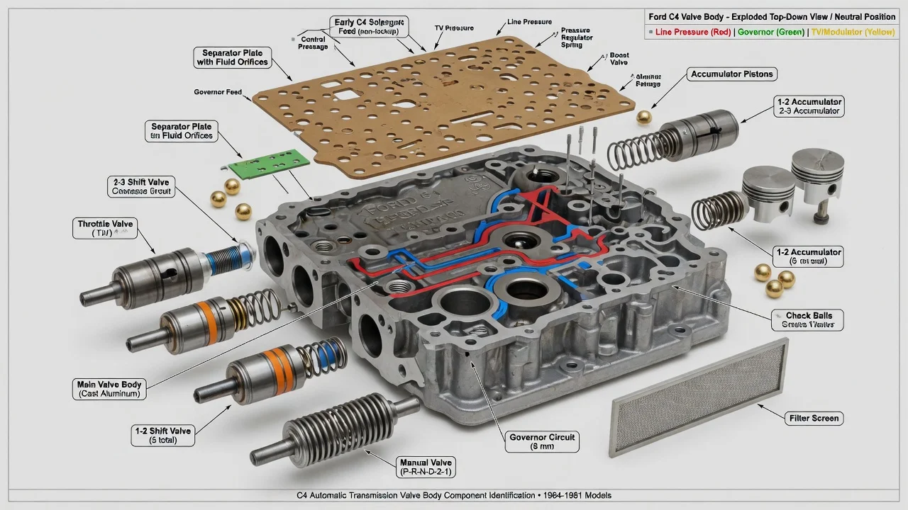
The Ford C4 transmission valve body is the hydraulic control center of the three-speed automatic Ford built from the mid-1960s into the early 1980s. A diagram helps you match each valve, spring, check ball and plate to its place. The exact layout depends on the year and calibration of your unit, though. This guide covers what a typical C4 valve body contains, how its parts work together, and how to identify components without guessing.
The short answer
On a C4, the valve body bolts to the bottom of the transmission case, under the oil pan. It is built as an upper and a lower body. Between them sits a separator plate with gaskets, and the oil screen mounts underneath. Each body half has machined bores holding spool valves and springs, held in place by retaining plates or pins. Check balls sit in pockets on one side of the separator plate. The most reliable C4 transmission valve body diagram is the exploded view in a Ford shop manual for your model year. The instruction sheet in a quality rebuild or shift kit made for your unit is a good alternative. Those sources show each bore, the valve order, the spring locations and the check ball positions.
One qualification matters most. No single diagram matches every C4. Many valves look alike, and springs that seem identical can differ in length and tension. Separator plates and check ball positions changed across years and applications. Use a generic diagram to learn the layout, then confirm every detail against information for your specific transmission before you reassemble anything.
Main components you will find
A typical Ford C4 valve body includes these parts. The manual valve is moved by the shift linkage through the inner manual lever. Line pressure regulating and boost valves control overall hydraulic pressure. The 1-2 and 2-3 shift valves decide when upshifts happen. The downshift valve responds to the kickdown linkage. Throttle-related valves respond to the vacuum modulator. Depending on the version, there are also smaller timing, backout or accumulator-type valves that smooth the transfer from one gear to the next. The separator plate's metering holes, the gaskets and the check balls complete the hydraulic circuit. Each part depends on correct position to work.
Many diagrams also show parts that interact with the valve body but are not part of it. These include the vacuum modulator and its actuating rod, the kickdown lever on the outside of the case, the governor on the output shaft, the intermediate and low-reverse servos, the bands and the clutch packs. Keep this distinction in mind when ordering parts or reading a parts breakdown. A valve body kit will not include these external components.
How the valve body controls shifts
The front pump supplies fluid, and the regulating valves set line pressure. The manual valve routes that pressure according to the selector position. Road speed acts through the governor, which produces pressure that rises as the vehicle goes faster. That governor pressure pushes on the shift valves. Spring force and throttle-related pressure push back. When governor pressure wins, a shift valve moves and redirects fluid. For second gear, fluid goes to the intermediate servo, which applies the intermediate band. For third gear, fluid goes to the reverse-high clutch while the band is released. Reverse uses the reverse-high clutch and the low-reverse band. Manual low holds the low-reverse band in addition to the forward clutch.
The vacuum modulator senses engine load through manifold vacuum. Low vacuum under heavy throttle raises throttle pressure, which delays upshifts and makes them firmer. The kickdown linkage moves the downshift valve to force a lower gear when you press the pedal fully within the allowed speed range. Orifices in the separator plate and the check balls control how quickly fluid applies or exhausts. A misplaced ball or the wrong plate can therefore change shift timing or shift feel.
What changes the answer for your transmission
The production period matters. Early C4 units used a dual-range selector pattern with two drive positions, and later units used a select-shift pattern. The manual valve and related circuits differ between these designs. Calibrations also varied with engine and vehicle application, which affects springs and separator plates. The later C5, which added a lockup converter, is a different design, so its valve body diagram should not be used for a C4. Aftermarket manual-shift or reverse-pattern race valve bodies have their own layouts and follow the maker's documentation, not Ford's.
Service history can make a factory diagram misleading. Older cars often carry swapped transmissions. Many C4s have had shift kits installed, which can mean drilled separator plates, changed springs or removed check balls. For correct fitment, identify the unit from its identification tag or other markings rather than assuming it matches the original car. If parts in your valve body don't match the diagram, consider that it may have been modified before you assume something is missing.
Diagnostic codes generally do not apply here. The C4 is a fully hydraulic transmission found in vehicles that predate onboard transmission trouble codes. Diagnosis relies on a road test, fluid inspection, line pressure readings and modulator vacuum checks. Fluid specification also varies. Many units originally called for Type F, and some later applications specified a different Ford fluid. Confirm the correct fluid for your transmission from the dipstick marking or service information.
What the owner can do
Start outside the valve body. Check the fluid level and condition using the procedure in your manual. Inspect the modulator vacuum hose for leaks, and look for transmission fluid inside the hose, which can point to a leaking modulator. Verify the kickdown and manual linkage adjustment, and check band adjustment against specification. Write down the shift behavior in detail: which shift is affected, at what speed, at what throttle, and whether it changes when the transmission is cold or hot. Those notes narrow the diagnosis more than any single symptom does.
If you remove the valve body to identify or clean components, first drain the pan and remove the screen. Lower the valve body level so that check balls and the manual valve do not fall out. Photograph both sides before you separate the halves, and mark the check ball locations on your diagram. Then work on one bore at a time. Lay the valve, spring and retainer from each bore in order on a clean surface, and tag any springs that look similar. Clean the parts with solvent and lint-free materials. A clean valve should move freely in its bore without force. Never file or force a sticking valve without first understanding why it sticks.
Repair options vary with what you find. A dirty valve body can often be cleaned and reassembled with new gaskets made for that version. Shift kits change shift firmness but require following their instructions exactly. A used or rebuilt valve body should be matched to your unit's identification. Debris, burnt fluid or friction material in the pan usually means the problem goes beyond the valve body. Tighten all bolts to the specified torque in the correct sequence, because overtightening can distort the bodies and cause sticking valves.
Limitations and next step
This overview cannot replace the exploded view, spring identification, check ball map and torque values for your exact transmission. Get those from service information or from kit instructions made for your unit. A symptom such as a harsh shift, a missing third gear or delayed engagement does not prove the valve body has failed. Worn bands, clutches, seals, a faulty governor, a leaking servo or a weak pump can produce similar complaints. If a fluid and linkage check does not resolve the problem, a transmission specialist with a pressure gauge can test the hydraulic circuits and tell you whether the valve body is really at fault before you spend money on parts.