Ford AOD Valve Body Diagram and Component Identification
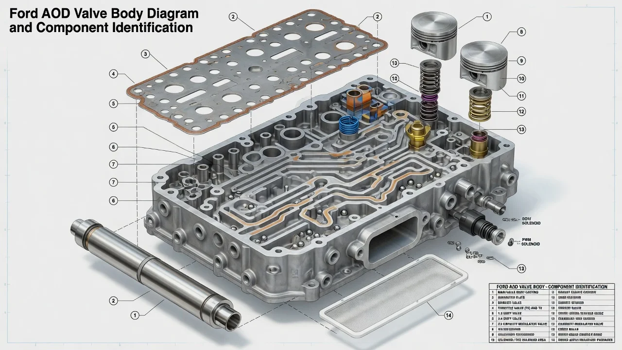
The Ford AOD is a four-speed automatic overdrive transmission that shifts entirely by hydraulic logic, so its valve body is the control center for every upshift, downshift and line pressure change. A diagram helps you identify the valves, springs, separator plate and check balls before you remove or reassemble anything. This guide explains what those diagrams show, how the parts work together, and why the exact transmission version matters before you trust any single drawing.
What an AOD valve body diagram shows
A typical Ford AOD transmission valve body diagram shows three things: the casting viewed from the passage side, the separator plate with its gaskets, and an exploded view of each valve bore with its valve, spring, sleeve or plug and retainer in installation order. Many service drawings also mark the locations of the check balls, which sit in pockets of the casting or case and are easy to lose or misplace during disassembly.
The main components you will be asked to identify are the manual valve, which is moved by the inner manual lever when the driver selects a range; the throttle valve and its plunger, which respond to the throttle valve linkage; the shift valves that control the 1-2, 2-3 and 3-4 changes; and the regulating and limiting valves that shape pressure and shift timing. The fluid filter attaches to the bottom of the valve body, and the whole assembly bolts to the underside of the case beneath the oil pan. Exact valve names, spring identification and check ball positions differ between drawings and production revisions, so a diagram is only reliable when it matches your unit.
How the AOD valve body controls shifts
The AOD has no shift solenoids. Shift timing comes from a balance of forces on each shift valve: governor pressure, which rises with vehicle speed, pushes toward an upshift, while throttle pressure and spring force resist it. Light throttle lets governor pressure win early, producing low-speed upshifts; heavier throttle raises throttle pressure and delays the shift. At wide-open throttle the same throttle valve system triggers forced downshifts, because the AOD uses its throttle valve linkage instead of a separate kickdown linkage.
Throttle pressure also influences line pressure, which determines how firmly clutches and bands apply. This is why throttle valve linkage adjustment is so important on this transmission. If throttle pressure is too low, shifts can come early and soft, and apply elements may slip under load. If it is too high, shifts can be late and harsh. The separator plate and check balls route fluid between circuits and control the direction and rate of flow, so a missing check ball or wrong plate can change shift behavior even when every valve moves freely.
Configurations that change the diagram
First confirm the transmission type. The original AOD uses a throttle valve cable or rod and has no electronic shift control. The later AODE and the related 4R70W look similar from the outside but are electronically controlled, with a wiring connector on the case and a solenoid assembly on the valve body. Their valve bodies, separator plates and check ball layouts are not interchangeable with the hydraulic AOD, and a diagram for one will mislead you on the other.
Within the hydraulic AOD, production changes over the model years affected valve bodies, separator plates and gaskets, and calibrations differed by vehicle and engine application. A plate or gasket must match both the case and the casting it mounts to; mixing revisions can block or open passages that the design never intended. Aftermarket shift kits and performance valve bodies add another layer, since they may replace springs, drill plate holes or delete check balls. If the unit has been rebuilt, the service history matters as much as the original build, so check identification tags, casting marks and any rebuild paperwork before matching a diagram or ordering parts for fitment.
Using the diagram during inspection or repair
Before disassembly, photograph the valve body in place, note the check ball positions as soon as the plate is lifted, and lay parts out in the order they come out of each bore. Springs that look similar can have different rates, so keep each spring with its valve. Compare what you find against the diagram rather than forcing your parts to match the drawing; if they differ, you may have a different revision or a modified unit, and that difference should be identified rather than corrected by guesswork.
When inspecting, look for valves that stick or bind in their bores, scored surfaces, debris in passages, broken springs, damaged gaskets and a warped or nicked separator plate. Fluid condition is also informative: heavy contamination or friction material in the pan suggests internal wear that a valve body service alone will not fix. Use the fluid specification listed for your model year, since the original Ford specification for older AOD units has been superseded, and follow the service manual's bolt tightening sequence and torque values to avoid distorting the casting.
Before blaming the valve body, verify the simpler causes of poor shift behavior: correct fluid level and condition, throttle valve linkage adjustment, a working governor and secure linkage at the manual lever. The engine computer does not command AOD shifts, so engine diagnostic codes will not directly identify an AOD shift fault, although engine performance problems can still affect how the transmission feels.
Limits of a generic diagram and next steps
A generic diagram is useful for orientation, but it cannot confirm which revision you have, what a previous rebuilder changed or which component has actually failed. Symptoms such as harsh shifts, delayed engagement or missing overdrive can come from the valve body, but also from throttle linkage adjustment, the governor, worn clutches or bands, sealing problems or a torque converter issue. Treat the symptom as a starting point and confirm the cause with inspection or pressure testing before replacing parts.
For reassembly specifications, check ball locations for your exact unit and line pressure testing procedures, use the factory service manual for your vehicle and model year or the instructions supplied with a specific shift kit. If the transmission shows heavy contamination, slipping in several gears or damage beyond the valve body, a transmission specialist can perform pressure tests and recommend repair options, from valve body service to a full rebuild or replacement.