Exhaust Gas Temperature Sensor Codes P2466 to P2495 Explained
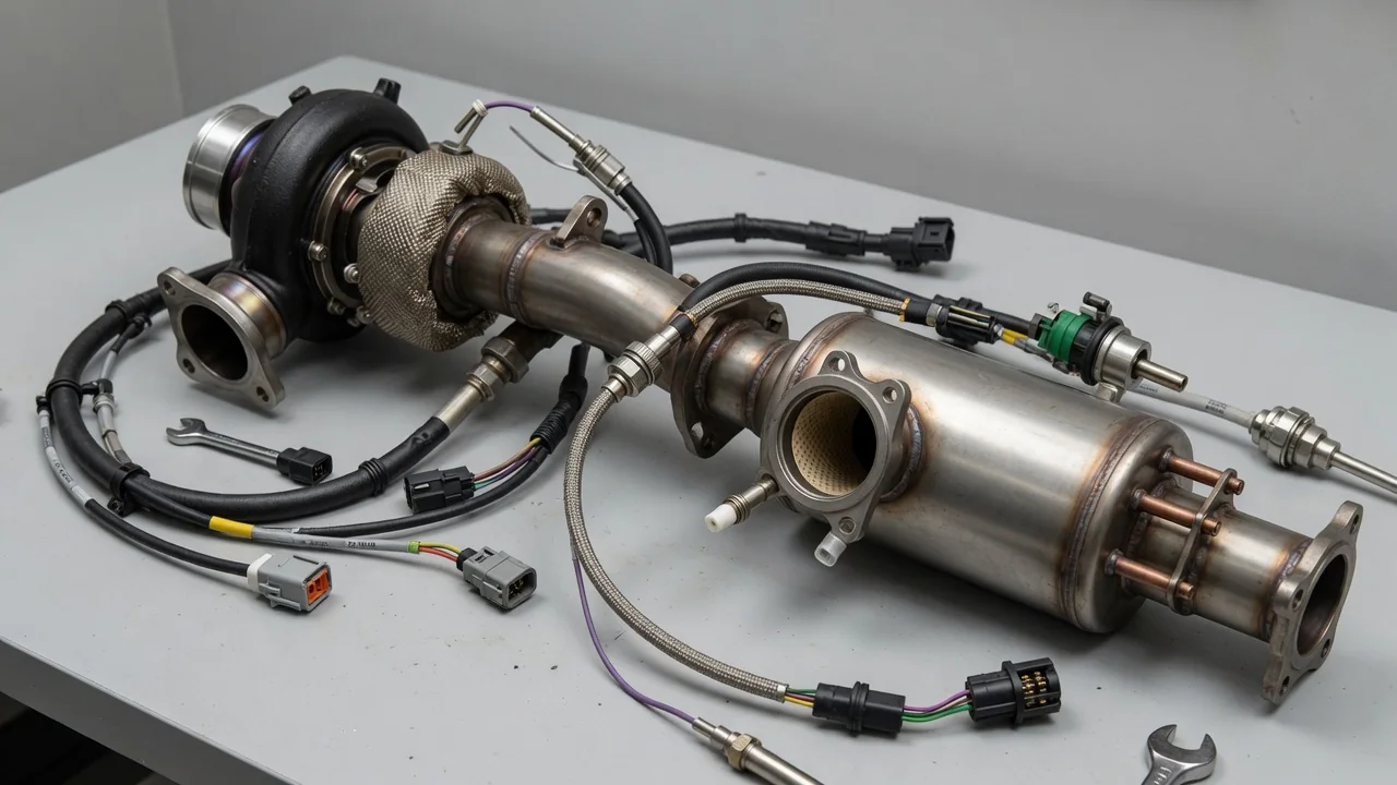
A P2493 code indicates an exhaust gas temperature sensor circuit fault, but the exact meaning depends on the vehicle’s make, model, and engine. These sensors help the powertrain control module manage diesel particulate filter regeneration and turbocharger protection. Misinterpreting a code can lead to unnecessary parts replacement, so confirming the detailed description and understanding the sensor’s location are essential first steps before any diagnostic work.
Confirm the Code Definition and Sensor Location
Before interpreting any code from P2466 through P2495, you must obtain the complete definition for your specific vehicle year, make, model, and engine. Many of these numbers are manufacturer-dependent, meaning the same code can refer to different sensors or fault categories depending on the platform. Service information will state whether the code applies to an exhaust gas temperature sensor circuit or another monitored component. Never assume that a code number alone identifies a failed part.
Exhaust layouts determine bank and sensor numbering. On V-style engines, bank 1 and bank 2 refer to the cylinder head sides; on inline engines, bank 1 is typically the only bank. Sensors are often counted from the engine outward, with sensor 3 and sensor 4 located downstream in the exhaust aftertreatment system. A code is only a record of a monitored condition. It tells you the control module saw a signal outside expected parameters, but it does not prove that the named sensor is defective—connector, wiring, or software issues can produce the same code.
P2466–P2474: Identify the Reported Circuit Fault
In many applications, P2466 designates exhaust gas temperature sensor circuit low on bank 1 sensor 3, while P2467 is circuit high for the same location. P2468 can indicate sensor 3 circuit intermittent, and P2470 often applies to bank 1 sensor 4 circuit low. P2471 is typically bank 1 sensor 4 circuit high, P2473 may be bank 1 sensor 4 circuit intermittent, and P2474 can refer to bank 2 sensor 3 circuit low—but these definitions require confirmation in service data because they are not universal.
The words open, low, high, range/performance, and intermittent describe electrical behavior, not actual exhaust temperature. A low circuit reading may mean the signal voltage is near ground, but that could result from a shorted harness or a sensor measuring genuinely cooler gas. A high circuit reading could be an open sensor or wiring, not an overheating condition. Range/performance faults indicate the signal is changing in an implausible way. Diagnostic steps should therefore begin with connector inspection, wiring checks, and live data comparison before condemning any component.
P2479 and P2481: Investigate Reported Excessive Temperature
P2479 and P2481 indicate an exhaust gas temperature out of range or too high condition for a specific sensor location, but the exact monitored spot and threshold vary by manufacturer. Some systems use these codes when the sensor reports a temperature that is higher than expected for current engine operation, while other systems may use them for actual overtemperature during regeneration. Confirming the vehicle-specific description prevents misdiagnosis between a false high reading and genuine excessive heat.
A reported overtemperature condition must be investigated from two directions. First, verify the sensor’s accuracy by comparing it to nearby temperature sensors and known cold-soak values. Second, assess actual exhaust operating conditions—an active regeneration event naturally raises exhaust temperatures, and faults in fuel injection, turbocharger control, or EGR can cause unintended high temperatures. Clearing the code or replacing the sensor alone cannot prove an overheating condition is resolved; you must demonstrate that temperatures return to expected ranges under all operating modes.
P2482–P2486: Trace the Specified Sensor Circuit
P2482 through P2486 often cover exhaust gas temperature sensor circuit faults for sensor 5 and beyond, but manufacturers assign the exact bank and sensor position differently. P2482 may be bank 1 sensor 5 circuit low, P2483 circuit high same sensor, P2484 circuit intermittent bank 1 sensor 5, while P2485 could be bank 2 sensor 4 circuit low and P2486 bank 2 sensor 4 circuit high. Always verify these definitions using the correct wiring diagram; a generic scan tool label may omit the bank or sensor number.
Damaged insulation, loose terminals, connector contamination, and internal sensor faults can all affect the temperature signal. Heat, vibration, and road debris attack the wiring harness near the exhaust, causing intermittent connections that produce a range of codes. Freeze-frame data captures the conditions when the fault set, including engine load, speed, and temperature, which helps determine whether the problem occurs only during regeneration or high-load driving. Confirm the exact connector identity before inspection because multiple temperature sensors on the exhaust can be visually similar and easy to confuse.
P2489–P2495: Resolve the Exact Meaning Before Testing
The codes P2489 through P2495 are often assigned to exhaust gas temperature sensor circuit range/performance or intermittent faults for upper sensor positions, but each code must be verified individually. For example, P2493 frequently indicates exhaust gas temperature sensor circuit intermittent on bank 2 sensor 3, while P2492 may be bank 2 sensor 3 circuit high, and P2494 could be bank 2 sensor 4 circuit low. However, these descriptions vary by vehicle manufacturer and engine calibration, so inferring definitions from adjacent numbers is unsafe.
Generic scan-tool descriptions are abbreviated and can lack the bank, sensor position, or fault type. Without the full definitions from service information, you may test the wrong sensor or ignore a range/performance condition that points to wiring degradation rather than a sensor failure. Related codes can provide context—a circuit high on one sensor and circuit low on another might suggest a shared power or ground issue. Use live temperature data from all sensors to see which signal is implausible, and never treat multiple codes as proof that multiple sensors have failed simultaneously.
Symptoms, DPF and Turbo Risks, and Driving Decisions
A faulty exhaust gas temperature sensor may trigger a check engine light, reduce engine power, or prevent diesel particulate filter regeneration. Some drivers notice no change in drivability at all, especially with an intermittent fault. Because the engine control module relies on these temperatures to protect the turbocharger and manage aftertreatment, an incorrect signal can stop regeneration, cause excessive soot accumulation, or allow exhaust temperatures to climb beyond safe limits without proper warning.
Unreliable temperature information can interfere with aftertreatment control, but genuine excessive heat poses a direct threat to the exhaust components, DPF substrate, and turbocharger bearings. A stored code alone cannot establish component damage or tell you how far you can safely drive. If you see smoke, smell burning, notice severe power loss, or receive an explicit stop warning, pull over safely and shut off the engine. Follow the vehicle’s warning instructions; continuing to drive during an overheating event can turn a sensor problem into expensive hardware failure.
Safe Observations and Professional Sensor Testing
Before clearing any diagnostic information, record all codes, freeze-frame data, warning messages, and the operating conditions present when the fault set. This information may include engine speed, vehicle speed, coolant temperature, and exhaust temperature readings from other sensors. Clearing codes erases this evidence and forces you to reproduce the fault later. The freeze-frame data often reveals whether the problem is intermittent or consistent, which guides the next test and prevents unnecessary parts replacement.
Owner inspection should be limited to safely visible wiring and connectors after the exhaust has fully cooled. Never reach near hot components or crawl beneath a vehicle that is supported only by a jack. Professional testing begins with a visual inspection of the connector and harness, followed by live temperature data comparison during a cold start—all exhaust gas temperature sensors should read close to ambient coolant temperature after sitting overnight. A sensor that reads significantly different is suspect, but only a wiring diagram and manufacturer-specific procedures will reveal the correct resistance values and voltage thresholds for that exact sensor design.