Duramax Mass Air Flow Sensor: Location, Symptoms, and Replacement
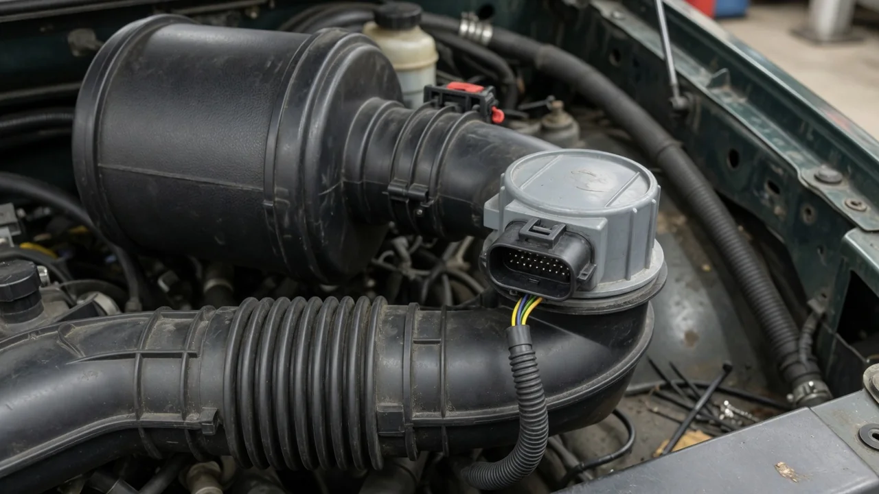
A Duramax mass air flow sensor issue can trigger driveability complaints and fault codes that point toward the intake tract rather than the turbocharger or fuel system. Owners of LB7, LBZ, LML, and L5P trucks often need to locate the MAF sensor before testing airflow readings or ordering a replacement. Because intake layouts differ across generations, a vehicle-specific check is the first step. The sensor measures incoming air mass, but symptoms alone do not prove it has failed.
What the Duramax MAF Sensor Measures
The Duramax MAF sensor sits in the intake path and reports how much air enters the engine. A heated wire or film cools as air flows across it, and the sensor’s electronics convert that cooling into a mass airflow value. The engine control module uses this signal along with intake air temperature, manifold pressure, and throttle position to set fuel delivery and EGR operation. If the signal drifts but stays plausible, the truck may feel down on power without setting a code quickly.
A trouble code such as a MAF rationality or circuit fault means the reported airflow did not match expected values under the operating conditions. That could be caused by a failing sensor, but it is equally possible with an intake leak after the sensor, a damaged air filter housing, or a wiring issue. Before replacing anything, record the exact code and freeze-frame data. Then identify the truck’s engine designation, model year, and intake configuration because diagnostic expectations change between an LB7 and an L5P.
Finding the Sensor in the Intake System
Start at the air filter housing on the driver or passenger side, depending on the generation, and follow the large intake duct toward the turbocharger. The MAF sensor is usually mounted in that duct shortly after the filter. Its body may be secured with two screws or a snap ring, and it has a multi-pin electrical connector on top or on the side. On a stock Duramax, the sensor is often the first electrical component in the intake path, but aftermarket cold air kits can move it.
To avoid confusing the MAF with an intake air temperature or boost sensor, look for the sensor body that sits perpendicular to the duct and uses a larger rectangular or oval connector. The sensing element is inside the bore, not a separate probe hanging far into the tube. With the engine off and cool, a visual inspection can confirm the location. Never reach near the fan or belt drive, and keep the ignition key out of the switch while checking the connector.
LB7 and LBZ Location and Identification Checks
On an LB7 Duramax, the MAF sensor is normally installed in the airbox outlet or the start of the intake duct on the driver side. The air filter housing is a black plastic box with spring clips, and the sensor mounts just after the filter element so it sees clean, filtered air. Its connector faces upward and may be covered by a small wire loom. The LB7 layout changed little during its run, but an early or late production variation can affect the airbox shape, so compare the service diagram to the truck.
An LBZ places the MAF in a different airbox design that often incorporates the filter minder and a larger outlet. The sensor is still in the duct leaving the filter, but the housing shape and mounting screw location differ from the LB7. Engine designation alone does not confirm fitment because a replacement sensor must match the calibration and connector index. Check the VIN, look at the old sensor’s part number if legible, and verify the intake duct is original before ordering a part.
LML and L5P Sensor Location and Fitment
For an LML, the MAF sensor is typically found in the intake duct between the air filter housing and the turbo inlet, near the inner fender on the driver side. A factory airbox uses a round or oval outlet that transitions into the duct, and the sensor may be held by two screws with a gasket underneath. Some LML models use a charge air cooler duct layout that puts the sensor after the air filter but before the turbo, not after the intercooler. Stock configuration matters because an EGR-equipped LML has additional flow calculations.
The L5P revised the intake system significantly, and the MAF location is often in the air filter housing outlet or a short duct section leading toward the turbo on the passenger side. The L5P filter is a large panel or cartridge in a rectangular housing, and the sensor connector may be hidden under the engine cover. Aftermarket intakes for the L5P frequently relocate the sensor into a new tube, sometimes requiring a calibration or a bracket. Confirm the identified component using the component diagram before unplugging it.
Symptoms and Checks Before Condemning the Sensor
A check-engine light, reduced power mode, hesitation, or a drop in fuel economy can all appear with a Duramax MAF problem, but those symptoms also come from boost leaks, EGR faults, or fuel pressure issues. Before condemning the sensor, open the hood and look for a split intake duct, a loose or corroded electrical connector, or an air filter that is not seated fully in its housing. Any gap after the sensor lets unmetered air enter the engine, and the ECM will fuel for a smaller air quantity than the engine actually ingests.
Record all stored codes and freeze-frame data before clearing anything. A P0101 on a Duramax means the MAF signal was out of expected range, but a weak turbocharger or a stuck EGR valve can create the same imbalance. Airflow readings in grams per second only mean something when compared against engine speed, boost, and intake air temperature; a scan tool snapshot at idle cannot prove the sensor is bad. If the truck has a severe miss or will not rev safely, park it and have the diagnosis done without further driving.
Cleaning, Replacement, and Confirming the Result
Cleaning a Duramax MAF sensor can help if the element is visibly coated with oily residue from an aftermarket filter, but it is not a universal fix. Only use a cleaner specifically labeled for MAF sensors, and never touch the wire or film with a brush, cotton swab, or finger. Do not use brake cleaner, carburetor cleaner, or compressed air, because the element is fragile and any damage changes the calibration. If the service manual does not allow cleaning for that model, replace the sensor instead.
A new MAF sensor must match the original part number for the engine and intake layout, and the connector must seat fully without bent pins. Reusing a damaged seal or a cracked duct will recreate the same code. After replacement, confirm the result by watching live data during a test drive: airflow should rise smoothly with throttle and match expected values at known engine speeds. Clearing the light is not confirmation; the truck must complete its readiness monitors and stay code-free under load.