CVT Transmission Speed Sensor Identification: A Practical Guide
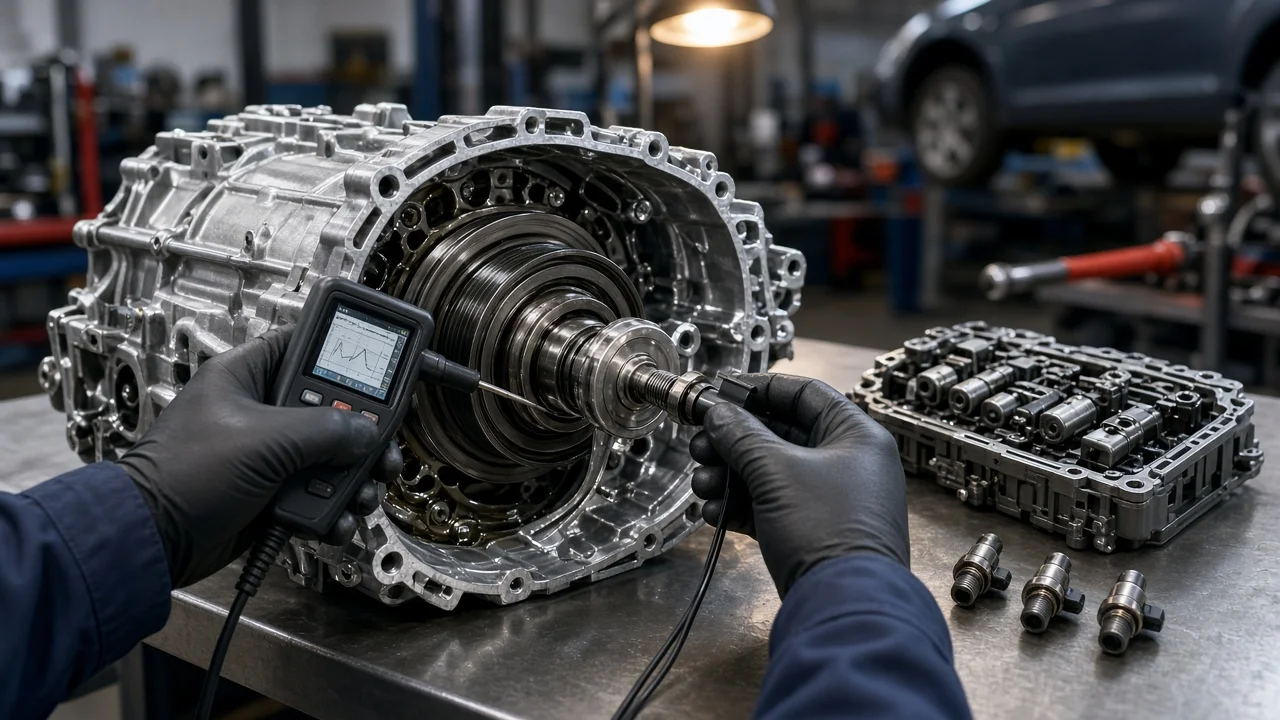
A CVT usually relies on more than one speed sensor, so identifying the right one starts with the transmission itself rather than the symptom. This guide explains which sensors a continuously variable transmission typically uses, how they report speed, what makes one vehicle's layout differ from another, and how an owner can narrow down the correct part before buying anything or approving a repair.
Which Speed Sensors a CVT Uses
Most CVTs use at least two transmission speed sensors. One reads the input side and is often called the primary pulley or input speed sensor. The other reads the output side and is often called the secondary pulley or output speed sensor. Some units add a turbine speed sensor when a torque converter is used, and many vehicles also share wheel speed data from the ABS system with the transmission control module. The module compares these readings to calculate the actual pulley ratio and to decide how the belt or chain should be clamped and positioned.
The direct answer to which sensor a given vehicle needs therefore depends on the transmission type, model code and production date. Sensor names are not standardized across manufacturers, and two sensors that look alike may not be interchangeable. Reliable identification comes from the VIN, the transmission identification and the part number, not from appearance or a symptom alone.
How CVT Speed Sensors Work
Each sensor faces a toothed wheel, gear or ring that turns with a shaft or pulley. As the teeth pass the sensor tip, it produces a pulsing signal whose frequency rises with rotational speed. Two common designs exist. A Hall-effect sensor is powered by the module, usually through three wires for supply voltage, ground and signal, and outputs a square-wave signal. A variable reluctance, or magnetic pickup, sensor generates its own alternating signal, typically through two wires, and its output strength grows as speed increases.
Because the module knows engine speed, input speed and output speed, it can detect slip between the belt and pulleys, verify that the commanded ratio is actually being achieved, and calculate road speed on vehicles where the transmission output signal feeds the speedometer or other modules. When one reading is missing, implausible or disagrees with the others, the module may store a code, limit ratio changes or switch to a protective fail-safe mode.
What Changes Sensor Identification
Several factors change which sensor applies and how it is replaced. The first is the exact transmission model, since one vehicle line can use different CVT families depending on engine, drivetrain and market. Production changes can also alter sensor part numbers, connector shapes or mounting positions within the same model year, which is why fitment should be confirmed by VIN rather than by year, make and model alone.
Location matters as well. On some CVTs the speed sensors bolt into the outside of the case and can be reached from under the vehicle or after removing a component such as an air box or battery tray. On others, one or more sensors sit inside the unit or belong to an internal assembly, which turns replacement into a much larger job. Whether the vehicle is front-wheel drive or all-wheel drive, and whether the transmission has a torque converter, also affects which sensors exist and where the speedometer signal originates.
Removing an externally mounted sensor can let some fluid escape, so the fluid specification matters even for a sensor job. CVT fluid is formulated for the friction needs of a particular belt-and-pulley design, and conventional automatic transmission fluid or the wrong CVT fluid can cause drivability problems. Level-check procedures also vary, and some require the fluid to be at a specified temperature read through a scan tool.
Symptoms and Codes Are Clues, Not Verdicts
Speed sensor faults can show up as a speedometer that drops out or reads erratically, a check engine or transmission warning light, unusual shift behavior such as RPM flare or harsh engagement, reduced power, or the transmission holding a fixed ratio in fail-safe mode. The same complaints can also come from low or degraded fluid, belt or pulley wear, a valve body or solenoid problem, a damaged connector, a chafed harness or a control module issue.
Diagnostic codes narrow the field but do not name a failed part. Generic codes such as P0715 for the input or turbine speed sensor circuit and P0720 for the output speed sensor circuit describe a signal or circuit problem, while manufacturer-specific codes add more detail. A circuit code can be caused by wiring, a loose connector or a module input just as easily as by the sensor itself. A ratio or performance code may even mean the sensor is reporting accurately and the transmission is genuinely slipping.
Steps to Identify the Correct Sensor
Start with the identification details. Record the VIN and look for the transmission model code, which is usually stamped on the case or printed on a tag or label; a dealer parts department can also decode it from the VIN. If a sensor has already been removed, its part number and connector pin count help confirm the match. Review the service history for recent fluid changes, transmission work or collision repairs near the wiring harness.
Next, read stored codes with a scan tool that can access the transmission control module, not only the engine module, and note any freeze frame data. Tools that show live data allow a useful comparison: while the vehicle is driven safely, input and output speed readings should change smoothly and track each other in a way that matches the reported ratio. A reading that drops to zero or jumps while the others stay steady points toward that sensor's circuit. Then inspect the connector and harness for corrosion, bent pins, fluid intrusion and damaged insulation.
If an accessible sensor is removed, check its tip. A light film of fine metallic particles can occur, but heavy debris suggests internal wear that a new sensor will not cure. Repair options then range from a connector or wiring repair to sensor replacement, and some vehicles need a relearn or adaptive reset with a capable scan tool afterward.
Limitations and When to Get Help
General descriptions cannot replace the service information for a specific vehicle. Sensor names, wire colors, resistance or voltage specifications, torque values, fluid fill procedures and relearn steps all differ by transmission, and guessing them risks damage or misdiagnosis. Electrical testing at the module connector can also cause harm if done with the wrong probes or procedure.
If codes return after a sensor replacement, the suspected sensor is internal, the fluid is dark or carries heavy debris, or the vehicle repeatedly enters fail-safe mode, a transmission specialist or dealer with factory-level diagnostics is the sensible next step. It is also worth checking whether the transmission is still covered by a powertrain or extended warranty before replacing parts, since coverage terms may affect who should perform the repair.