Cold Air Intakes and MAF Sensors: Adapter and Aftermarket Fitment
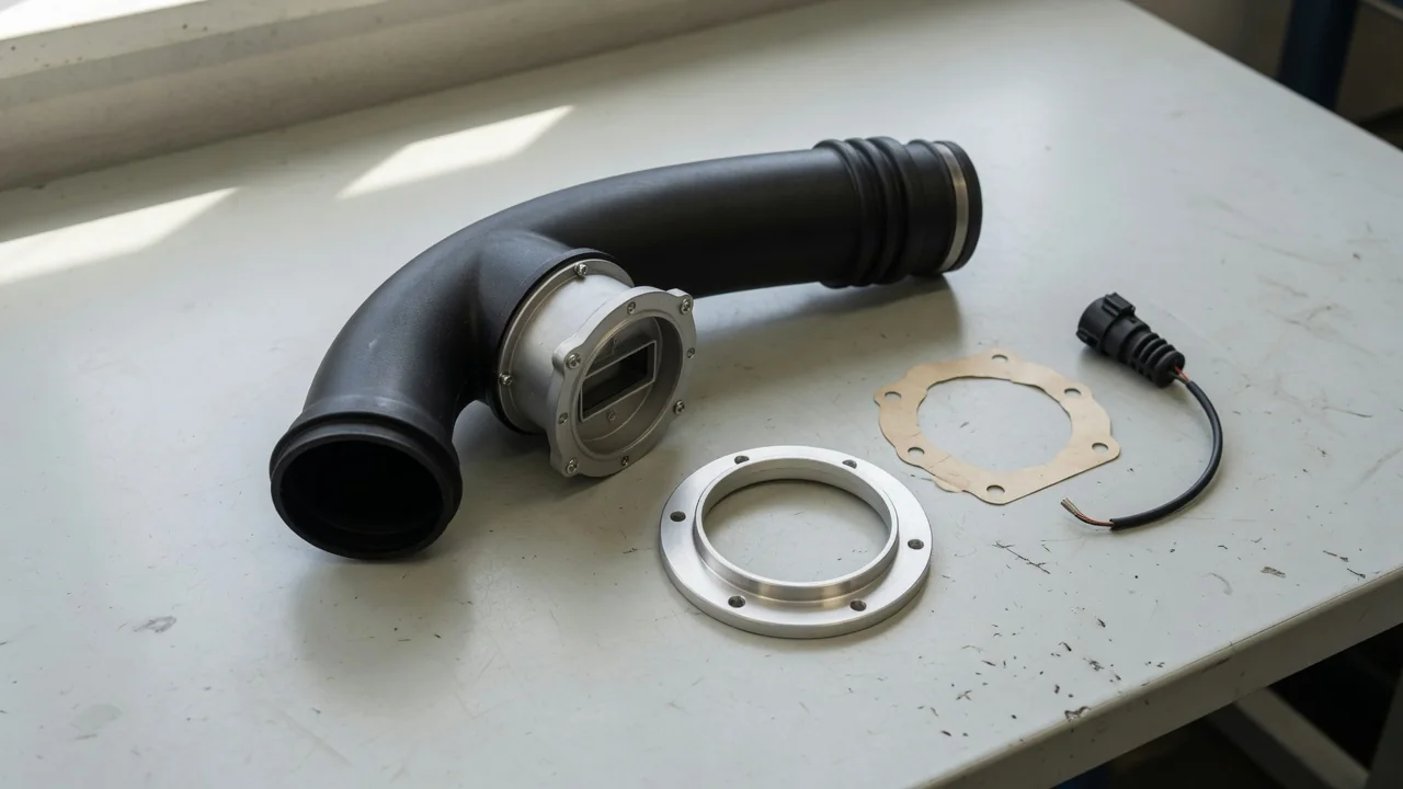
A cold air intake with a mass air flow sensor can change how the engine management system sees intake airflow, even when the hardware looks like a simple tube-and-filter swap. Anyone planning the modification needs to know when a mass air flow sensor adapter is required, how housing geometry affects the signal, and what an aftermarket mass air flow sensor has to match electrically and mechanically.
How an Intake Change Can Affect MAF Readings
On vehicles that meter incoming air with a mass air flow sensor, the engine control module uses that signal as a primary fueling input. The sensor reports how much air is moving through the intake tract so the module can command injector pulse width. A cold air intake mass air flow sensor arrangement still must present a usable, repeatable signal. If the relationship between actual intake airflow and the reported value shifts, fuel trims may compensate for a while, but the module is working from a changed picture of the air entering the engine.
MAF housing diameter, sensor position, nearby bends, and airflow turbulence all change how the element samples the stream. A larger tube can slow local velocity at the sensing element even when total mass flow is similar, and a sharp bend or poorly placed filter can create swirl the original calibration never saw. Physical bolt-up does not prove the signal still matches actual airflow, and it does not support a horsepower claim by itself. Unmetered air past a leaky joint has the same problem: the module never sees that air.
Check How the Intake Accommodates the Vehicle’s MAF Sensor
Before discussing fitment of a mass air flow sensor for a cold air intake, confirm the exact vehicle, engine, and intake application. Catalog photos and generic tube diameters are not enough, because sensor mounting flange geometry and housing length vary even among similar-looking engines. Some kits retain the original MAF housing and only change the filter and upstream tubing. Others provide a mounting location so the transferred sensor element can be relocated into a new tube. Verify the intended configuration against the kit instructions and the hardware in the box.
Intake documentation should be checked for sensor orientation, housing specifications, sealing provisions, and any stated sensor calibration requirements. Clocking of the element, insertion depth, and the direction of the airflow arrow all affect how the sample is taken. Look for notes on gaskets, O-rings, and intake tract sealing at every joint from the filter to the throttle body. If the instructions mention a calibration change, a reflash, or a different sensor, that requirement belongs to that application and should not be assumed for another vehicle even if the tube looks interchangeable.
When a MAF Adapter Is Required
A mass air flow sensor adapter is required when the intake tube, filter, or housing interface does not match the sensor hardware the vehicle actually uses. The adapter may join a sensor element to an intake tube, couple a complete MAF housing to a filter, or provide another application-specific interface shown in the kit. Its job is geometric: it fills a mismatch in diameter, flange pattern, or mounting style so the element sits in the airstream. Confirm which of those interfaces the part is meant to serve on a cold air intake with a mass air flow sensor.
Flange pattern, sensor insertion depth, orientation, gasket seating, and an airtight connection decide whether the adapter is usable. A rotated element, a shallow seat, or a crushed gasket can admit unmetered air or place the hot wire or film in a poorly representative part of the stream. An airtight connection at the sensor mounting flange and along the tube still does not rewrite the module's expected signal. A mechanical adapter does not automatically correct a calibration mismatch, and it does not establish electrical compatibility with the vehicle's connector, pinout, or sensor type.
Choosing a Sensor for a Cold Air Intake
Fitting a cold air intake does not automatically require replacing a functioning mass air flow sensor. Many kits are built so the original element or complete housing stays in service, and a working sensor that still reports cleanly should not be discarded just because the filter and tubing changed. Replacement becomes a separate decision when the original unit is damaged, contaminated, or electrically out of range. Treat the mass air flow sensor and cold air intake as a measurement system first, not as a reason to buy a new sensor.
Check whether the intake was designed around the vehicle's existing sensor and its expected housing geometry, including MAF housing diameter and the location of the element in the tube. A kit that relocates the sensor into a different bore or closer to a bend is asking the original calibration to interpret a new flow field. Any stated need for a different sensor or revised calibration requires application-specific support from the intake documentation and a qualified specialist who can evaluate that vehicle. Generic advice to run a larger MAF is not a substitute for that confirmation.
What to Verify Before Buying an Aftermarket MAF Sensor
An aftermarket mass air flow sensor has to match the exact vehicle and engine application, not a similar-looking intake tube. Confirm the connector and pinout, the sensor design, and whether the supplied part includes its housing or is only the element that bolts into an existing body. Some units are complete housings with a molded sensor mounting flange; others are transfer-style elements. A housing-inclusive part that changes MAF housing diameter or internal contour can alter the signal even when the electrical plug fits, so the mechanical package and the electronics have to be checked together.
The sensor's signal characteristics and intended housing must match what the engine management system expects, because the module interprets voltage or frequency against a calibrated curve. A part that plugs in but was built for a different bore or transfer function can drive fuel trims toward the edge of their correction range. Useful purchase information includes traceable part identification, application documentation, warranty coverage, and return terms if the unit is the wrong configuration. Unsupported performance claims are not a substitute for that paperwork, and compatibility should not be inferred from a listing title alone.
Recognizing Problems After an Intake Change
After an intake change, rough idle, hesitation, stalling, or a check-engine light can appear without proving that the mass air flow sensor has failed. Those symptoms can also come from a disturbed seal, a loose clamp, a connector that was not fully seated, or unmetered air entering downstream of the element. With the engine off and cool, limit owner checks to safe visual observations: look for loose connectors, visibly disturbed seals, and disconnected intake hoses. Do not probe live circuits, spray solvents into the sensor, or drive with the intake left open while guessing at the cause.
Diagnostic codes, fuel trims, and airflow data need vehicle-specific interpretation, because a manufacturer-dependent code is evidence to read, not proof a part has failed. Professional leak testing and a calibration assessment may be necessary when intake tract sealing looks intact but the module still reports implausible airflow. Stop driving if stalling, severe loss of power, or a flashing check-engine light occurs, and seek professional help. Do not bypass the sensor, jumper its connector, or leave it unplugged to keep the vehicle moving; that removes a primary fueling input and can create further drivability and emissions problems.