C0050, C0051, and C0052 Codes: Verify Meaning and Diagnose
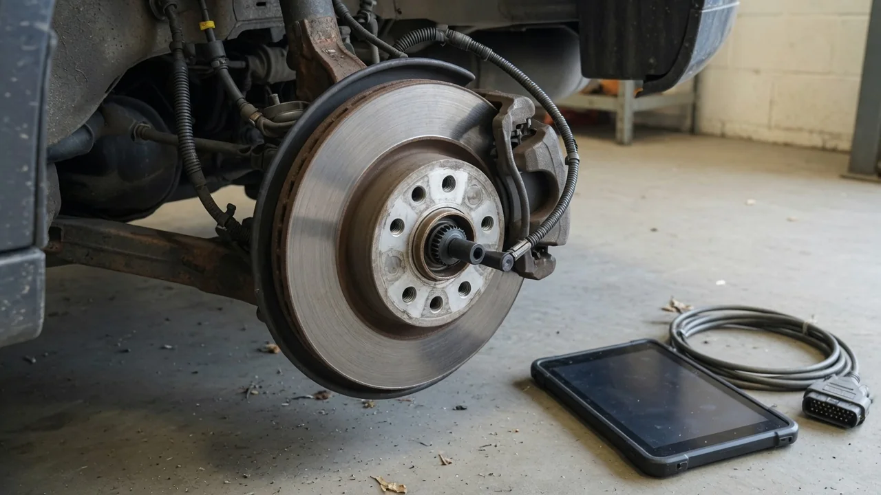
A C0050 code, a C0051 code, and related chassis identifiers such as C0052 and C0054 are diagnostic trouble codes that need vehicle-specific confirmation before any wheel location or component is assigned. On some vehicles these entries involve a right rear wheel speed sensor circuit reported by the ABS control module, but that mapping is not universal. Treat each stored message as evidence to interpret, not as proof that a sensor has failed.
Verify the Vehicle-Specific Meaning of C0050
Interpreting C0050 starts with the vehicle's year, make, and model, the module that reported the diagnostic trouble code, and the complete description published in that vehicle's service information. Chassis codes are manufacturer-dependent, so a generic scanner label is not enough. Confirm whether the reporting source is the ABS control module or another chassis controller, then read the full text rather than relying on the numeric identifier alone. Only when that documentation names the right rear wheel speed sensor circuit should diagnosis proceed under that interpretation.
A circuit-related C0050 code identifies a diagnostic concern in the monitored path, not a confirmed failed sensor. Wiring, connector condition, the encoder ring, the sensor itself, or the control module can all produce similar stored results. Record any suffix, failure type, or snapshot data the scan tool displays, because those details can change the required path from a continuity check toward a signal-quality or correlation test. Clearing the message before that information is saved can erase the only clue that distinguished an intermittent circuit fault from a continuous one.
Establish What C0051 and C0052 Identify
C0051 and C0052 also require verification of vehicle-specific meaning before anyone assigns a wheel location, a component, or a failure condition. Adjacent numbers do not establish that these identifiers are right rear wheel speed sensor sub-codes of C0050. On one platform the C0051 code may describe a different circuit, polarity, or performance condition than C0052, while another platform may use those numbers for an unrelated chassis function. Preserve the scanner's complete code text and the reporting module name so later testing follows the documented definition rather than a guessed pattern.
Where applicable service information does link C0051 or C0052 to the right rear sensor system, use the documented trigger for each entry rather than a universal definition. One message may point to an open or short in the sensor wiring harness, another to an implausible wheel speed comparison, and a third to a failure type that only appears with a specific operating condition. Those distinctions matter because they steer the technician toward harness inspection, live-data comparison, or a different circuit test. Do not merge the codes into a single failed-sensor conclusion.
Keep C0054 Within Its Verified Diagnostic Context
C0054 likewise needs a vehicle-specific definition and cannot inherit meaning from sitting near C0050, C0051, or C0052 on a code list. Numerical proximity is not diagnostic evidence. Include C0054 in a right rear wheel speed discussion only if the applicable service information establishes that connection for that year, make, model, and module. If the published description names a different circuit, actuator, or chassis function, that boundary must be respected even when several chassis codes set at the same time.
When C0054 concerns another system, keep its diagnosis outside this sensor-circuit scope. Shared warning lamps or a common ABS control module freeze-frame can make unrelated codes look like a family, but each identifier still follows its own documented test. Record C0054 with its full text so it is not discarded or misfiled as a wheel speed sub-code. If later documentation shows it is related, it can be brought back into the same work order; until then, treating it as a right rear sensor fault risks replacing the wrong part.
Recognize Warning Lights and Driving Concerns
When a verified wheel speed fault affects antilock, traction, or stability functions, some vehicles illuminate an ABS lamp, a traction control warning, or a stability indicator, while others use a combined chassis message. Not every vehicle behaves the same way, and the lamp pattern cannot identify the failed component. Perceived brake behavior is equally inconclusive: a firm pedal does not prove that modulated braking is available, and a longer stop or a pulsing pedal does not by itself prove a sensor, harness, or module failure.
Consult the owner's manual for the meaning of illuminated warnings and for any instruction to reduce speed or seek service. Avoid assuming that normal pedal feel confirms full braking-system operation, because conventional hydraulic braking can remain while antilock and traction functions are limited. If braking feels reduced, the pedal is abnormal, or a brake warning specifically calls for stopping, pull over when it is safe and arrange assistance. Do not continue a trip solely because the vehicle still rolls and the C0050 family of codes has not been decoded yet.
Gather Safe Observations Before Testing
Before any testing, record when the warning appeared, whether it is intermittent, and whether recent wheel, tire, brake, or hub work preceded it. Timing is useful context, not proof of cause. Save every accessible ABS control module code, including C0050, C0051, C0052, and C0054, along with current or stored status, freeze-frame data, and failure type, before clearing anything. Some basic readers cannot reach chassis or ABS information at all; if the tool only shows powertrain codes, the chassis messages may still be present in the module.
Limit owner checks to what is visible with the vehicle parked, on a level surface, and without lifting it, removing parts, or reaching near moving components. Look for obvious damage to a sensor wiring harness, a disconnected or corroded connector, or debris packed around a visible sensor head if those areas can be seen without disassembly. Wiring damage, poor connector condition, a sensor fault, or encoder-ring damage may warrant professional investigation when the confirmed code definition points at that circuit. Leave raised-vehicle inspection and electrical probing to a qualified technician using the published procedure.
Understand Professional Testing and Repair Confirmation
A technician starts with the verified code description and the vehicle's service procedures, then uses wheel speed live data to decide the next step. Comparing all four wheel-speed signals under the conditions the service information specifies can show a drop-out, a stuck reading, or a correlation error without immediately condemning a part. Circuit and signal testing stays at a high level for a reason: sensor design, whether passive, active, or integrated in a hub, determines suitable methods, and indiscriminate probing can damage the sensor or the ABS control module.
Sensor replacement should follow evidence, not the presence of C0051 or a related chassis code alone. Hub or encoder-ring involvement must be established for the specific vehicle, because some designs place the tone ring on the hub, axle, or bearing assembly. Repair confirmation includes the required system checks, restored signal operation in live data, and a drive cycle that shows the codes do not return. Clearing a traction control warning or ABS lamp without those checks does not confirm a repair; stored C0050, C0051, C0052, or C0054 can reappear on the next key cycle.