C0035 and C0036 ABS Codes: Meaning, Symptoms, and Safe Checks
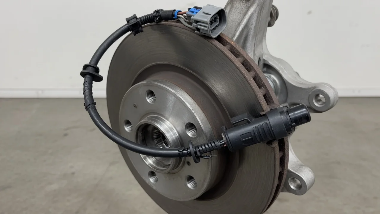
A C0035 code is chassis diagnostic information from an antilock brake system, and a C0036 code may appear with it or separately. Neither is a universal part diagnosis. Meaning depends on year, make, model, and the complete module readout. Interpreting these faults starts with that context, then symptoms, possible wheel speed sensor issues, and cautious checks.
Verify What C0035 Means for the Vehicle
Before treating C0035 as a left-front wheel speed sensor problem, record the vehicle year, make, model, and the complete ABS module code, including any suffix or failure-type information. On some applicable vehicles, C0035 identifies a left front wheel speed sensor circuit fault, but that assignment is manufacturer-dependent. Confirm the definition in that vehicle's service information. A generic code list can mislabel the wheel, the circuit, or even the system, which sends diagnosis in the wrong direction from the start.
A circuit code identifies a monitored problem, not a confirmed failed part. C0035 can set from an open, short, or implausible wheel speed sensor circuit condition without proving the sensor itself needs replacement. Wiring, connectors, and module monitoring all sit on the same path. Treating the C0035 code as automatic sensor replacement skips that distinction and can leave the actual interruption untouched. Vehicle-specific confirmation is required before assigning meaning, wheel location, or a repair direction.
Confirm C0036 Before Calling It a Performance Sub-Code
C0036 is a separate stored identifier until vehicle-specific service information proves otherwise. The C0036 code is not a universal performance sub-code of C0035, and it should not be assumed to name the same wheel, the same circuit, or even the same failure type. Some platforms use C0036 for a different sensor, a different condition, or additional fault detail. The exact definition and the conditions that set it belong in that vehicle's ABS documentation, not in a shared guess across brands.
The full scanner readout, originating module, and any code suffix help distinguish a standalone C0036 from extra failure-type information attached to another chassis code. ABS scan data should show which controller stored the fault, whether both C0035 and C0036 are present, and whether a suffix describes circuit, performance, or communication behavior. That complete picture prevents treating two unrelated identifiers as a matched pair. Until those details are confirmed, C0036 remains a code to interpret, not a proven performance companion of C0035.
Recognize Warning Lights and Changes in Braking Assistance
An ABS warning light, a traction control lamp, or a stability control message can appear when the module loses a usable wheel speed signal, but available functions and warning behavior depend on the vehicle. Some systems disable antilock braking, traction control, or related assistance together; others keep hydraulic braking while limiting electronic aids. A stored C0035 or C0036 code does not by itself describe which lamps will illuminate or which features remain active. Watch the cluster and note every message rather than assuming a single standard pattern.
Abnormal traction intervention or a low-speed pedal pulsation can warrant investigation, yet those sensations cannot establish the failed component. Follow the owner's manual for warning-light guidance. Stop driving if braking feels impaired or a red brake warning appears, because that combination can indicate a more serious hydraulic or parking-brake concern rather than a chassis sensor code alone. Remaining roadworthy does not mean the antilock or traction systems are fully available. Treat reduced electronic assistance as a reason for diagnosis, not as permission to ignore the lights.
Understand Sensor, Wiring, and Hub-Related Causes
A wheel speed sensor, the sensor wiring harness, and the connectors between them share the monitored path that can set C0035 or C0036. Physical damage, a pinched or chafed harness, a loose connection, corrosion, or moisture can interrupt the signal without destroying the sensor body. An intermittent sensor signal is common when a connector is only partly seated or when water enters a damaged boot. Those conditions still look like a circuit or performance fault to the module, which is why the stored code is evidence of a monitoring event, not proof of a failed sensor.
On designs that read a tone ring or magnetic encoder ring at the hub, a cracked, missing, or contaminated ring, or excessive hub bearing movement, can distort wheel speed information. Those mechanical causes apply only where the vehicle's sensor arrangement uses that target. Hub noise or a stored code alone cannot establish that the bearing, hub assembly, or sensor is responsible. Recent wheel, brake, or hub work is useful diagnostic history because harness routing and sensor position can be disturbed, yet that history does not prove the work caused the fault.
Make Safe Observations Before Professional Testing
Before any code is cleared, record which warning lights appeared, what the driver felt, when the fault occurs, and any recent repair history. That snapshot is more useful than a blank module after a reset. An ABS-capable scanner may be needed because a basic engine-code reader may not access the relevant chassis module. Capture freeze-frame or equivalent ABS scan data if the tool provides it. Clearing C0035 or C0036 too early can erase the only evidence of an intermittent sensor signal.
Owner inspection should stay limited to visible, safely accessible wiring damage or loose routing with the vehicle parked and powered off. Do not lift the vehicle, disassemble the hub, or probe electrical circuits as a do-it-yourself step. Look only at harness sections that can be seen without removing parts, and note pinched, stretched, or unclipped sections near the wheel. Absent visible damage does not rule out an intermittent electrical fault or a sensor signal problem deeper in the circuit. Those findings still need professional testing.
Use Testing to Choose and Verify the Repair
Professional evaluation should compare live wheel speed data, circuit integrity, sensor signals, and encoder or bearing condition using that vehicle's procedures. Sensor design determines which electrical tests are valid. A two-wire passive sensor and an active sensor with a power supply are not interchangeable test subjects, so a universal resistance check is unsuitable and can mislead. ABS scan data that shows a drop-out on one wheel, a missing encoder pattern, or a circuit reading that disagrees with service information still requires confirmation before a part is selected.
Evidence must point to a sensor, harness, connector, or hub repair before that work is chosen. Parts are not always separately replaceable or interchangeable, especially when a sensor is integrated into a hub bearing assembly. Replacing the wrong item because C0035 or C0036 was stored can leave the encoder ring, wiring, or connector fault in place. After a justified repair, verification includes checking for returning codes and confirming normal system operation through the professional validation procedure specified for that vehicle, not a short test drive alone.