Brake Rotor Replacement: Procedure and Installation Checks
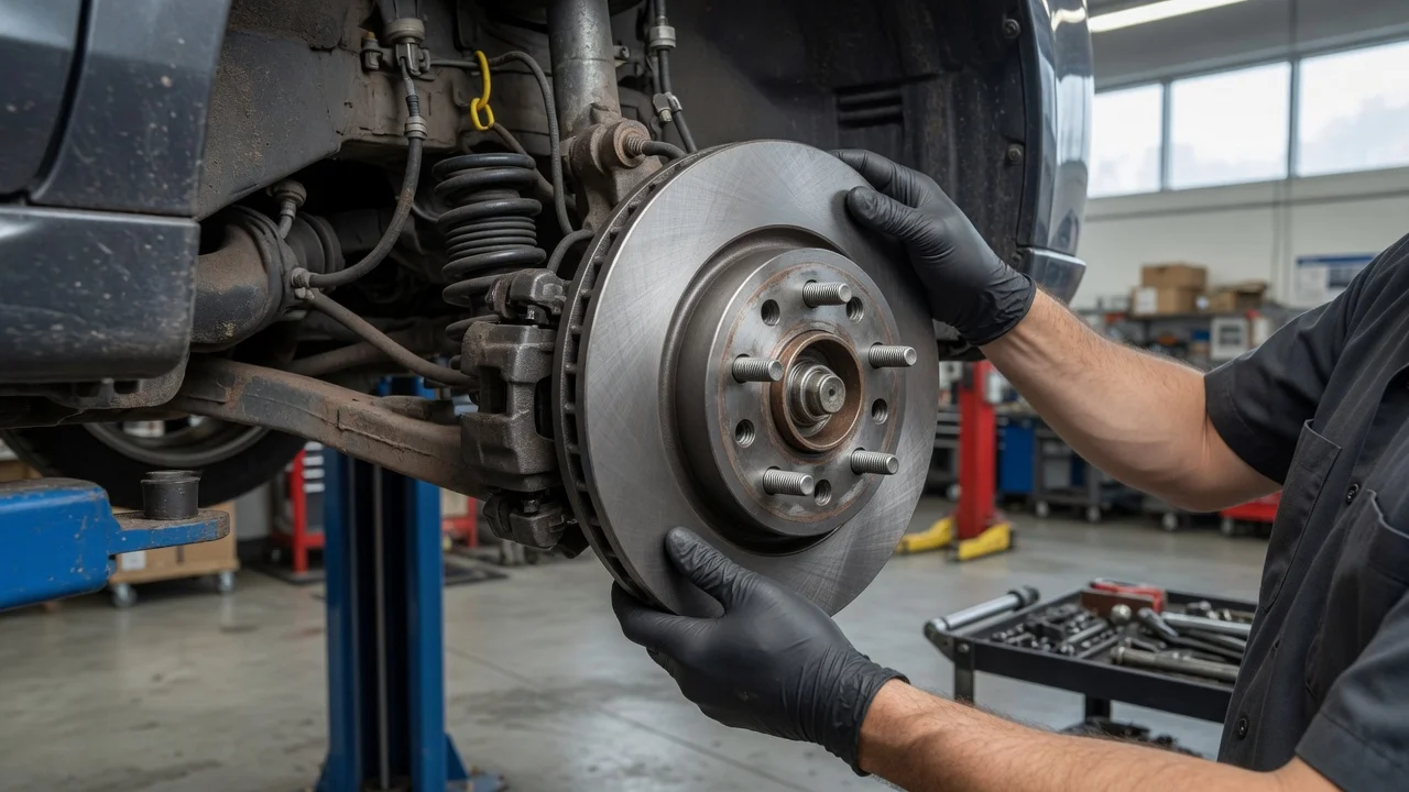
What brake rotor replacement covers
Replacing a brake rotor, also called a brake disc, means removing the wheel and caliper, freeing the worn disc from the hub, fitting a new disc, and reassembling the pads and hydraulic hardware so that axle can stop the vehicle as designed. On cars and light trucks with disc brakes, the rotor is the wearing metal surface that the pads clamp. The work is an axle-pair job: both front discs, or both rear discs, are changed together so left-to-right braking stays even.
Pads are replaced with the rotors. A new disc against a worn pad leaves an uneven contact patch and can score the fresh friction surface. Fastener torque, minimum disc thickness, allowable lateral runout, pad wear limits, electronic parking-brake retract steps, and bed-in instructions vary by model year, generation, powertrain, trim, and brake package. Those figures belong in the manufacturer’s workshop data for the exact vehicle; they are omitted here because they cannot be verified from this article alone.
When the disc needs to come off
Change the rotor when it is at or below the discard thickness stamped on the hat or rim, when it is cracked, deeply grooved, or heat-spotted, or when pedal or steering pulsation remains after the hub and disc have been measured. Many late-model discs are already close to minimum thickness when new and are sold as one-time, often coated, parts; those are replaced as complete discs. A rotor that still has usable thickness and sits within the published runout and thickness-variation limits can be machined on a lathe, and that choice rests on a micrometer and dial-indicator reading rather than appearance alone.
A vibrating pedal or wheel under braking, grinding from metal-to-metal contact, a pull to one side, or a raised lip at the outer edge of the swept face commonly lead owners to this job. The same symptoms can come from pads, a sticking caliper, a wheel bearing, or tires, so confirm the disc itself before ordering parts.
Tools, parts, and when to stop for a workshop
Gather the equipment and matching parts first, and treat electronic parking-brake (EPB) and hydraulic work as hard stops if you lack the tool or the published procedure.
Floor jack and axle stands rated for the vehicle, with wheel chocks; Lug socket and a torque wrench that covers wheel-fastener and caliper ranges in the service data; Sockets or hex/Torx bits for caliper guide pins and bracket bolts; C-clamp, rewind tool, or the manufacturer piston tool; many rear pistons must be rotated as they retract; Brake cleaner, wire brush, and a scraper for the hub flange; Dial indicator and magnetic base if you will measure hub or rotor runout; Brake fluid matching the specification on the master-cylinder cap or in the owner’s manual, used only if the level must be corrected after piston rewind; Scan tool with EPB service mode when the rear calipers are motorized
Parts are a matched pair of rotors for that axle, a matching pad set, new abutment clips or hardware when the kit includes them, and brake-specified slide lubricant. Confirm diameter, hat height, bolt circle, vented or solid construction, and any left/right or directional marking against the old disc before you strip the corner. A damaged rotor retaining screw is replaced with the disc.
Use a workshop when the EPB will not retract without a scan tool you do not have, a piston will not rewind, the hub flange is damaged or the wheel bearing has play, a hose or hydraulic fitting must be opened, or an ABS tone ring integral to the disc is damaged. Opening the hydraulic system adds bleeding, contamination, and modulator risks that this sequence does not cover. The same applies if torque, discard thickness, and EPB steps for that vehicle are unavailable.
Safety that applies before the first fastener
Work on level ground, chock the wheels that stay down, and support the vehicle on stands after it is raised. Wear eye protection. Dampen brake dust with brake cleaner and wipe it; compressed air spreads the dust. Keep fluid off paint, and leave the reservoir cap on except when you check or adjust the level. With a caliper off the disc, keep the pedal untouched unless that vehicle’s rewind procedure requires a controlled application. For an EPB, enter the manufacturer’s pad-replacement or service mode before spreading a rear piston; forcing a motorized caliper damages the actuator.
Replacement procedure
Complete one axle at a time with identical new discs and pads on both sides. Precautions sit in the step they affect.
Confirm the new rotors match the axle, diameter, hat, and venting, and that directional or side-stamped discs are identified left and right. With the vehicle on the ground, loosen the wheel fasteners, then raise and support that corner or the full axle on stands. Remove the wheel. Measure the old disc thickness at several points around the swept face with a micrometer and compare it with the discard value marked on the rotor. Note scoring, bluing, or cracks. Remove the caliper. On a floating design this is usually the two guide-pin bolts; on a fixed design it is the body bolts. Hang the caliper from the suspension with a hook so the hose stays slack and untwisted. If the pads are being replaced with the discs, remove them. If the caliper bracket traps the rotor, unbolt the bracket from the knuckle. Remove any hat retaining screw. Free a rust-bonded disc with penetrating oil at the hat-to-hub joint and a rotor puller, keeping impact off the friction face. Inspect the hub flange and the wheel bearing. Clean the flange to flat, bare metal; rust scale under the hat creates runout that feels like a warped new disc. Correct bearing play or a damaged flange before the new rotor goes on. Check caliper slides, pin boots, and the piston boot. A seized slide or sticking piston will drag the new pads and overheat the new disc; service or replace that caliper first. Clean pad abutments and fit new clips from the pad kit. Apply brake-specified lubricant only where the manufacturer allows it, typically pins and pad ears, keeping it off friction material and the disc face. Prepare the new rotor per the part maker: many coated, ready-to-fit discs are installed as supplied, while storage oil on an uncoated disc is removed with brake cleaner. Confirm vane or slot direction for side-specific discs. Seat the rotor fully on the cleaned hub. Fit the retaining screw, if used, to the published torque. The hat should sit flush, with no rock. Refit the caliper bracket if it was removed and tighten those structural bolts to the specified torque and, where required, angle. Install the new pads in the correct inboard and outboard positions, including any wear indicator or pad-wear sensor on the side the vehicle uses. Rewind or compress each piston only far enough to clear the new pad stack. Many rear pistons must be rotated as they retract so the parking-brake mechanism stays timed. Watch the reservoir; the level will rise. Remove fluid if it approaches the maximum mark. Refit the caliper over the pads and disc. Start guide pins or caliper bolts by hand. Tighten them to the specified torque. Confirm floating pads still have the designed small movement and that boots are untwisted. Refit the wheel. Tighten fasteners in the published pattern and in stages. Apply final wheel torque with the vehicle on the ground unless the manual states another method. Repeat the same parts and torque sequence on the other side of the axle. Pump the brake pedal until it is firm. The pedal travel takes up piston clearance. Set the reservoir to the specified mark with the correct fluid type and confirm there are no leaks at boots and hoses. A closed hydraulic system is normally complete once the pedal is firm; a soft pedal still needs diagnosis before the vehicle is driven. If an EPB was placed in service mode, restore it with the published sequence and confirm it applies and releases.
Installation checks before a road test
Work this list on both sides of the axle. A heavy drag, a spongy pedal, a warning lamp, or an EPB that will not restore are reasons to stay off the road until they are resolved.
Hub flange clean; rotor hat fully seated with no gap or rock; New disc matches the application and sits above discard thickness as a new part; Directional or side-stamped discs on the correct side; Pad material free of grease and oil; wear indicators and sensors routed as designed; Caliper slides free; boots intact and untwisted; Every caliper, bracket, retainer, and wheel fastener present and torqued to the published values; Brake hose slack, untwisted, and clear of the wheel; Parking brake, cable or EPB, applied and released through full travel; Pedal firm after several applications, with the engine running or off as that manual requires; Fluid level between the marks; cap sealed; Wheel turns with only light pad rub; If measured, lateral runout at the specified radius is within the published limit, with the disc clamped as the manual describes (some procedures use the wheel or a hat adapter)
First miles and bedding the new pair
New pads and discs need a controlled bedding sequence so transfer film builds evenly across the swept face. Speeds, number of decelerations, and cool-down are specified by the pad maker or the vehicle manufacturer; use that card. After the first heat cycle, recheck wheel-fastener torque and look again for leaks or a pull. Pedal pulsation that appears immediately after a rotor change is often a dirty hub or a disc that never seated; recheck hat seating and runout before changing the new disc.
Figures that still come from the service data
Generic torque or thickness numbers are unsafe substitutes. Look up each of the following for the exact vehicle and brake package.
Item Why it is vehicle-specific; Wheel-fastener torque and dry or lubricated condition Stud size, seat type, and coating differ by wheel package; Caliper guide-pin torque and pin lubrication Pin diameter and whether the pin is a stretch or coated design; Caliper-bracket to knuckle torque, including torque-plus-angle Structural bolts may be one-time-use on some generations; Rotor retaining-screw torque Hat screw size and whether it is a locking type; Discard thickness and any machine-to thickness Stamped on the disc and repeated in the brake chapter; Maximum lateral runout and thickness variation Measured at a published radius with a defined clamp method; Brake-fluid specification DOT grade is marked on the reservoir cap and in the owner’s manual; EPB service-mode steps Motorized rear calipers need the published retract and restore sequence; Pad and disc bedding sequence Friction compound and coating change the heat cycle
Those values can change with an optional heavy-duty or performance brake package on the same model. Using the wrong figure can stretch bolts, crack a hat, or leave a wheel under-torqued. With the axle reassembled, the pedal firm, the EPB restored, and the installation checks complete, the next action is a short road test in a safe area, followed by the published bedding sequence and a wheel-torque recheck.