Brake Line Replacement: Procedure and Requirements
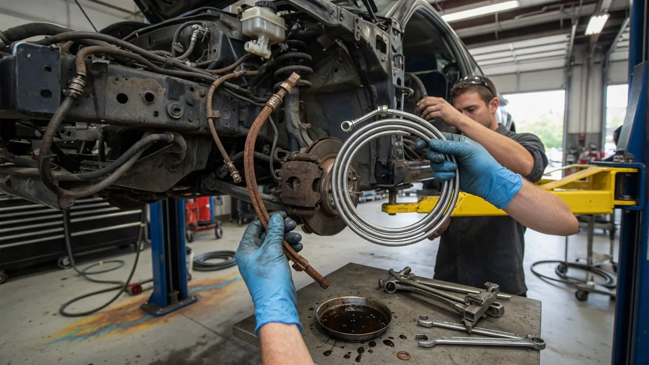
Replacing a brake line means removing a damaged, leaking or corroded section of the hydraulic brake circuit, installing a replacement that matches the original in material, outside diameter, flare type and fitting threads, then bleeding air from the system and confirming a firm pedal with no leaks. The job is achievable for a competent home mechanic on many vehicles, but it is safety-critical. Specifications, routing, bleed sequence and tightening values depend on the vehicle's make, model year, generation and brake system design. Vehicles with ABS or electronic stability control may need a diagnostic scan tool to bleed the hydraulic unit correctly.
What Counts as a Brake Line
Two different parts are commonly called brake lines. Rigid lines are metal tubes that run along the body and chassis from the master cylinder and ABS unit toward each wheel. Flexible brake hoses connect those rigid lines to the calipers or wheel cylinders and allow for suspension and steering movement. Hoses usually unbolt and are replaced as complete parts. Rigid lines often have to be cut, bent and flared, or replaced with pre-formed sections. This guide covers both, with most of the detail on rigid lines because they demand more preparation.
Signs a Line Needs Replacing
Visible fluid wetness or drips along a line, at a fitting or near a wheel; Heavy scaling, pitting or flaking corrosion on rigid lines, especially near clips and in areas exposed to road salt; Kinked, crushed or chafed tubing; Flexible hoses that are cracked, swollen, bulging or chafed; A brake pedal that feels soft or sinks, or a fluid level that keeps dropping without worn pads explaining it
A soft or sinking pedal can also come from a failing master cylinder, a leaking caliper or air in the system. Confirm the source before ordering parts. If a line is actively leaking, the vehicle should not be driven until it is repaired.
Requirements Before You Start
Match the Line Specification
A replacement line must match the original in four respects. The first is outside diameter, since vehicles use several tube sizes and the correct size varies by circuit and model. The second is flare type: the double (inverted) flare and the ISO bubble flare are the two common types, and they are not interchangeable because each seals against a matching seat. The third is fitting thread size and pitch, which can be imperial or metric depending on the vehicle and market. The fourth is length and routing, so the line clears exhaust heat, moving suspension parts and sharp edges. Check these details against the manufacturer's service information or the original part. Do not assume them from a similar vehicle.
Common replacement materials include coated steel, stainless steel and copper-nickel alloy tubing. Copper-nickel is popular for DIY work because it bends and flares easily and resists corrosion. Stainless steel is harder to flare and generally needs a tool rated for it. Pre-bent lines sold for a specific vehicle reduce bending and flaring work, but their fit should be checked against the original before installation.
Use the Correct Brake Fluid
Use the fluid grade specified by the manufacturer. It is normally printed on the reservoir cap or listed in the owner's manual. Glycol-based DOT 3, DOT 4 and DOT 5.1 fluids are used in most vehicles. Silicone-based DOT 5 is chemically different and must not be mixed with glycol fluids. Use fresh fluid from a sealed container, because glycol-based fluid absorbs moisture once opened. Brake fluid damages paint, so cover nearby painted surfaces and rinse spills with water promptly.
Tools and Supplies
Vehicle service information for routing, tightening values and bleed procedure; Jack and rated jack stands, plus wheel chocks; Flare-nut (line) wrenches in the correct sizes to avoid rounding fittings; Penetrating oil for seized fittings; Tubing cutter and deburring tool, if fabricating lines; Flaring tool that matches the required flare type and tube material; Tube bender for clean, kink-free bends; Replacement line or pre-bent section, correct fittings and any new clips; New sealing washers for banjo-type hose connections, where used; Caps or plugs to seal open lines and ports; Brake bleeding equipment: a clear hose and catch bottle, or a vacuum or pressure bleeder; Correct brake fluid, a drain pan and shop towels; Eye protection and gloves; A torque wrench, if the manufacturer specifies tightening values for the fittings; A diagnostic scan tool with ABS bleed functions, if the vehicle requires one
Step-by-Step Brake Line Replacement
1) Identify the failed section and trace its full route. Note how it is clipped and where it passes near heat or moving parts. On some vehicles, lines run above the fuel tank or through a subframe, and access may require lowering components. Consider professional service at that point. 2) Park on level ground, chock the wheels and raise the vehicle onto jack stands. Never work under a vehicle supported only by a jack. Remove wheels if needed for access. 3) Check the master cylinder reservoir level and keep it topped up throughout the job. Letting it run dry can draw air into the master cylinder or ABS unit and makes bleeding much harder. Some mechanics lightly depress and hold the brake pedal with a pedal holder to reduce fluid loss from open lines. 4) Soak the fittings with penetrating oil and allow time for it to work. Loosen fittings with flare-nut wrenches, holding the mating fitting or hose with a second wrench so the line does not twist. If a fitting is badly seized, the connected component, such as a hose or distribution block, may also need replacing. 5) Disconnect the line, remove it from its clips and immediately cap the open ports so dirt cannot enter and fluid loss is limited. 6) If fabricating a line, cut it square with a tubing cutter. Do not use a hacksaw, which leaves an uneven, burred end. Deburr the inside and outside edges and slide the fittings onto the tube in the correct direction before flaring. Form the flare with the correct tool and inspect it. The flare should be concentric, smooth and free of cracks or splits. Re-cut and re-flare any flare that looks off-center or damaged. 7) Bend the line to follow the original route using a tube bender, keeping bends smooth and free of kinks or flattening. Leave clearance from exhaust components, suspension travel and sharp edges. 8) Start each fitting by hand to avoid cross-threading, then tighten with a flare-nut wrench. Follow the manufacturer's tightening value where one is specified. Overtightening can crush the flare, and undertightening leaves a leak path. Secure the line in its clips or new clips. 9) For a flexible hose, check that it is not twisted after installation. Turn the steering lock to lock and, where possible, cycle the suspension to confirm the hose does not stretch, rub or contact the tire. Use new sealing washers on banjo fittings where the design calls for them. 10) Bleed the brake system using the manufacturer's procedure and sequence. Bleeding is covered in the next section. 11) Wipe all joints dry, reinstall wheels, tighten lug nuts to the manufacturer's specification and lower the vehicle.
Compression fittings are generally regarded as unsuitable for joining brake lines. Use properly flared joints with matching fittings, or replace the full line run if a suitable union is not available.
Bleeding the System
Any time a brake line is opened, air enters the circuit and must be removed. Air compresses under pressure, which produces a soft or sinking pedal and reduced braking. Common methods include a two-person manual bleed, a one-person vacuum bleeder and a pressure bleeder attached to the reservoir. Whichever method you use, keep the reservoir from running low, and continue at each bleeder screw until fluid flows with no air bubbles.
Bleed sequence varies by vehicle. A commonly cited order starts at the wheel farthest from the master cylinder, but many vehicles specify a different order, particularly those with diagonally split circuits or integrated ABS units. Some vehicles require a scan tool to cycle the ABS pump and valves during bleeding, especially if air may have reached the ABS hydraulic unit. Check the service information for the specific model year and system. If a scan-tool procedure is required and unavailable, this is a reasonable point to hand the job to a professional.
Completion Check
With the engine off, the brake pedal should feel firm and should not sink under steady pressure. On most vehicles with vacuum assist, the pedal travels slightly lower once the engine is running, which is normal. Have a helper hold firm pedal pressure while you inspect every disturbed joint and hose for wetness or drips. Confirm the reservoir is filled to the correct level and the cap is secure. Check that the brake warning light and any ABS warning lights are off. Test at low speed in a safe, open area before driving in traffic, confirming the vehicle stops straight and the pedal stays firm. Re-inspect the new joints after the first short drive and again after a few days of use.
When to Use a Professional
Professional service is a sensible choice if lines run above the fuel tank or require subframe removal, if multiple fittings are seized or corroded into adjoining components, or if the vehicle requires a scan-tool ABS bleed you cannot perform. It is also the safer option if you lack a flaring tool suited to the tubing material, or if the pedal remains soft after bleeding. Extensive corrosion on one line often indicates similar wear elsewhere, so a full inspection of the brake hydraulic system is worthwhile before replacing a single section.
Information Gaps to Fill for Your Vehicle
This guide does not give specific tube diameters, fitting thread sizes, flare types, tightening values, bleed sequences or fluid grades, because these vary by manufacturer, model year, generation and market, and no vehicle-specific data was available. Confirm each of these in the manufacturer's service information for your vehicle before starting work.