Brake Caliper Replacement: Procedure and Installation Checks
What the job covers
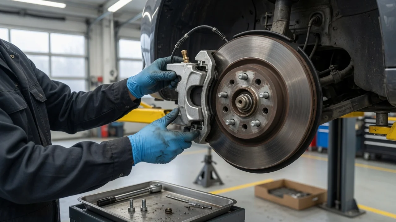
Replacing a brake caliper means removing the hydraulic clamp that presses the pads against the rotor and installing a new or remanufactured unit, then restoring a sealed, fully bled hydraulic circuit so pedal firmness and clamping force return. The work is done at one corner or more and is almost always paired with new pads on that axle. A rotor that is grooved, heat-spotted, or below the stamped minimum thickness is typically replaced or machined in the same visit.
The mechanical sequence is similar across passenger cars and light trucks, but several details change the answer in material ways: floating versus fixed calipers, whether the parking brake is a cable, an integral mechanical mechanism, or an electronic parking brake (EPB), and whether the hose uses a banjo bolt, a flare nut, or a quick-connect. Fastener torque, brake-fluid specification, bleeding order, and any EPB service-mode or relearn steps are vehicle-specific. Those values belong in the manufacturer’s workshop data for the model year, generation, axle, powertrain, and market. This guide is the common procedure and the installation checks that follow. It does not replace that service information.
When a caliper is the part that needs replacing
A caliper is due for replacement when a piston is seized or slow to retract, a dust boot is torn and the piston is corroded, fluid is leaking at the piston seal, banjo, or bleeder, slide pins or bushings are frozen so a floating housing cannot center, an internal parking-brake mechanism will not apply or release, or the casting is cracked. Uneven pad wear, a pull under braking, one wheel that runs much hotter than its pair, or a drip on the inboard face of the wheel are typical clues. Confirm them on the vehicle: a collapsed hose, a sticking slide on an otherwise sound caliper, or a damaged rotor can present the same way.
Set the parts list before the vehicle is in the air. Pads on the axle are replaced as a set. A matching caliper on the same axle is often renewed when corrosion or mileage is shared, so clamping force stays balanced. Replace the hose if it is cracked, swollen, internally restricted, or if its sealing faces are damaged when the old unit comes off. On many floating designs the bracket, slide pins, boots, and clips are separate from the caliper body; confirm whether the replacement is a loaded caliper (pads included) or a bare housing, and whether a hardware kit is required.
Prerequisites, tools, and parts
Work on level ground with the remaining wheels chocked. Support the vehicle on rated stands or a lift after it is raised; a jack alone is not a support. Keep the master-cylinder reservoir from running dry once any hose is opened, because air drawn into an ABS hydraulic unit can force a scan-tool bleed. Have the workshop data in hand before the first fastener is loosened. Brake fluid damages paint and some plastics, so keep a drain bottle under the union and wipe spills immediately. Do not reuse crush washers on banjo fittings.
Manufacturer workshop data for this vehicle: caliper, bracket, guide-pin, banjo or flare-nut, bleeder, and wheel-nut torque; fluid specification; bleed sequence; EPB service mode if fitted; Floor jack and rated jack stands, or a lift; Lug wrench and sockets that fit the caliper, bracket, and guide-pin fasteners; Line wrench for flare nuts where the hose uses a tube nut; Torque wrench covering the ranges published in the service data; Catch bottle, a syringe or similar tool to lower reservoir level, and unopened fluid of the specified DOT grade; Bleeder (vacuum, pressure, or two-person pedal method as the manufacturer allows) and a scan tool if an ABS modulator cycle or EPB retract is required; C-clamp or piston compressor; an EPB-compatible retract tool or scan tool on electrically applied rear calipers; Brake cleaner, the specified high-temperature slide-pin lubricant or brake grease, and new copper or aluminum crush washers; Replacement caliper, pads, hardware, and any hose, rotor, or bracket kit the inspection calls for
Precautions at the steps they affect
Do not open the hydraulic system until the reservoir can be kept above the minimum mark for the rest of the job. Do not let a disconnected caliper hang on the hose; support it with a hook or wire so the hose is not stretched or twisted. Do not compress a piston back into a caliper you intend to reuse while the hose is still attached and the opposite boot is damaged, because contaminated fluid can be driven upstream; open a bleeder or disconnect the hose when the procedure requires it.
EPB calipers often will not retract with a clamp. Forcing the piston can damage the motor-gear unit. Place the system in the specified service or maintenance mode before the pistons are moved, and complete the relearn after installation. Vehicles with ABS, electronic stability control, or hill-hold may require a pressure bleed or a scan-tool cycle of the modulator after a caliper or hose change; bleeding only at the corner bleeders is not always sufficient. If a steel line is rusted through, a flare nut rounds off, or the pedal sinks with every bleeder closed, stop. Line repair, master-cylinder diagnosis, and ABS bleeding belong with a shop set up for those tasks.
Replacement procedure
Match the replacement unit to the corner (left or right, front or rear), piston count and diameter, hose-port thread, and parking-brake interface before the wheel is off. If the new caliper is shipped with a port plug, leave the plug in place until the hose is ready so residual fluid stays in the bore. Then follow this order, inserting the published torque and fluid values at the fasteners and fill points they apply to.
Look up wheel-nut torque, caliper-bolt and guide-pin torque, bracket-bolt torque, banjo or flare-nut torque, bleeder torque, fluid specification, bleed order, and any EPB or ABS service steps for this vehicle. If an electronic parking brake acts on the axle you are servicing, place it in service mode with the specified on-board procedure or scan tool. With the vehicle on the ground, loosen the wheel nuts. Raise and support the vehicle. Remove the wheel. Inspect the hose, bracket, slides, pads, rotor face and thickness against the stamped minimum, and the opposite caliper on the same axle. Adjust the parts list if the hose, rotor, or bracket is unserviceable. Remove a small amount of fluid from the master-cylinder reservoir so it will not overflow later, without emptying the reservoir. Place a drain bottle under the hose union. On a floating caliper, remove the guide pins or unbolt the caliper from the bracket. On a fixed caliper, unbolt the housing from the knuckle or adapter. Support the caliper so it does not hang on the hose. Disconnect the brake hose. Use a line wrench on a flare nut. Plug the hose and the caliper port at once. Discard banjo crush washers. Remove the bracket if the service procedure or the new kit requires it. Clean slide bores. Replace pins, boots, and bushings. Lubricate only with the brake-safe grease specified for those pins; petroleum grease swells the rubber. Fit any required brackets, a new bleeder if one is supplied, pad clips, and wear sensors. As installed, the bleeder must sit at the high point of the caliper so air can leave the bore. Install the bracket to the knuckle if it was removed and tighten it to the published torque. Install the new pads in the correct inboard and outboard positions, with shims and anti-rattle clips fully seated. On many sliding calipers the inboard pad locates on the piston. Place the caliper over the pads and rotor. Start every fastener by hand. Tighten guide pins or caliper bolts to the published torque. Guide-pin torque is often different from bracket-bolt torque. Attach the hose with new crush washers on a banjo, or thread a flare nut by hand first. Clock the banjo so the hose is not twisted. Tighten the union to the published value. Do not over-tighten a banjo into an aluminum housing. Route and clip the hose as original. Turn the steering from lock to lock and, with the suspension supported as it would sit on the road, confirm the hose cannot rub the wheel, spring, or control arm and is not stretched at full droop. Bleed the circuit in the manufacturer’s order, keeping the reservoir at the specified fluid grade and above the minimum mark. Close each bleeder to the published torque so the seat seals without stripping aluminum threads. Perform any required ABS modulator cycle or EPB apply-and-release during the bleed. Refit the wheel, snug the nuts, lower the vehicle, and tighten the wheel nuts in the published pattern and torque. Pump the pedal until it is firm before the vehicle is moved. Set the reservoir between the minimum and maximum marks and fit the cap. Complete any EPB relearn.
Installation checks
Complete these checks with the vehicle still supported or just lowered, before any road test. A firm pedal after pumping is necessary and not sufficient; the mechanical alignment, hose routing, and a dry hydraulic union are what keep the repair from failing on the first heat cycle.
Check Pass condition; Caliper position Housing is centered on the rotor; pads sit parallel to the disc; the piston boot does not touch the rotor hat; Slide function (floating calipers) Pins move in their bores; the caliper can be shifted slightly by hand and returns; Hose Clips engaged; no twist; clearance through full steering lock and suspension travel; Unions Banjo or flare, bleeder, and piston boot remain dry after several firm pedal applications; Bleeder At the highest point of the bore; cap installed; Wheel rotation Rotor turns with light new-pad drag, not locked and not grinding; Pedal Height and firmness return after pumping; the pedal does not sink at rest with the engine off; Parking brake Cable or integral mechanism applies and releases; an EPB completes its relearn without a stored fault; Warning lamps ABS, brake, or EPB lamps are not left on after the specified key or drive cycle; a lamp that stays on needs diagnosis; Fluid Level between marks with the cap sealed; only the specified glycol or silicone grade is in the reservoir
Completion check and first drive
The job is complete only when the hydraulic circuit is bled, every published torque is applied, the installation checks above pass, and the parking-brake system is restored. For the first movement, use a clear, low-speed area: confirm a firm pedal before rolling, then make several moderate stops. The vehicle should track straight, the pedal should stay firm, and no fluid odor or wet union should appear at a wheel. After a few stops, a brief hand check near the hub (not on a rotor face) can show whether one corner is much hotter than its pair, which points to a hose, slide, or piston that is not releasing.
Bed the pads using the pad or vehicle manufacturer’s instructions when they are supplied. If none are supplied, a widely used general practice is a series of moderate decelerations from low speed without holding the vehicle stopped on hot brakes, followed by a cool-down drive. That practice is not a substitute for a published bedding procedure and is not a tested result for any specific pad compound.
Values that remain in the vehicle’s service data
No single torque, fluid grade, or bleed order applies across models. Do not carry numbers from another vehicle or from memory. Take the following from the manufacturer’s data for the exact vehicle, and treat their absence as a stop point rather than a guess: caliper-bolt, guide-pin, bracket, banjo or flare-nut, bleeder, and wheel-nut torque; whether a loaded caliper includes hardware; rotor minimum thickness and runout; brake-fluid specification (DOT 3, DOT 4, DOT 4 low-viscosity, DOT 5.1 glycol, or DOT 5 silicone are not interchangeable by habit, and silicone DOT 5 is incompatible with glycol systems); bleed sequence and whether the ABS unit must be cycled; and EPB retract, service-mode, and relearn steps. Where that data is not in hand, the safe next action is to obtain it or have the hydraulic portion of the job completed by a shop that has it.