Allison Transmission Output Speed Sensor Location
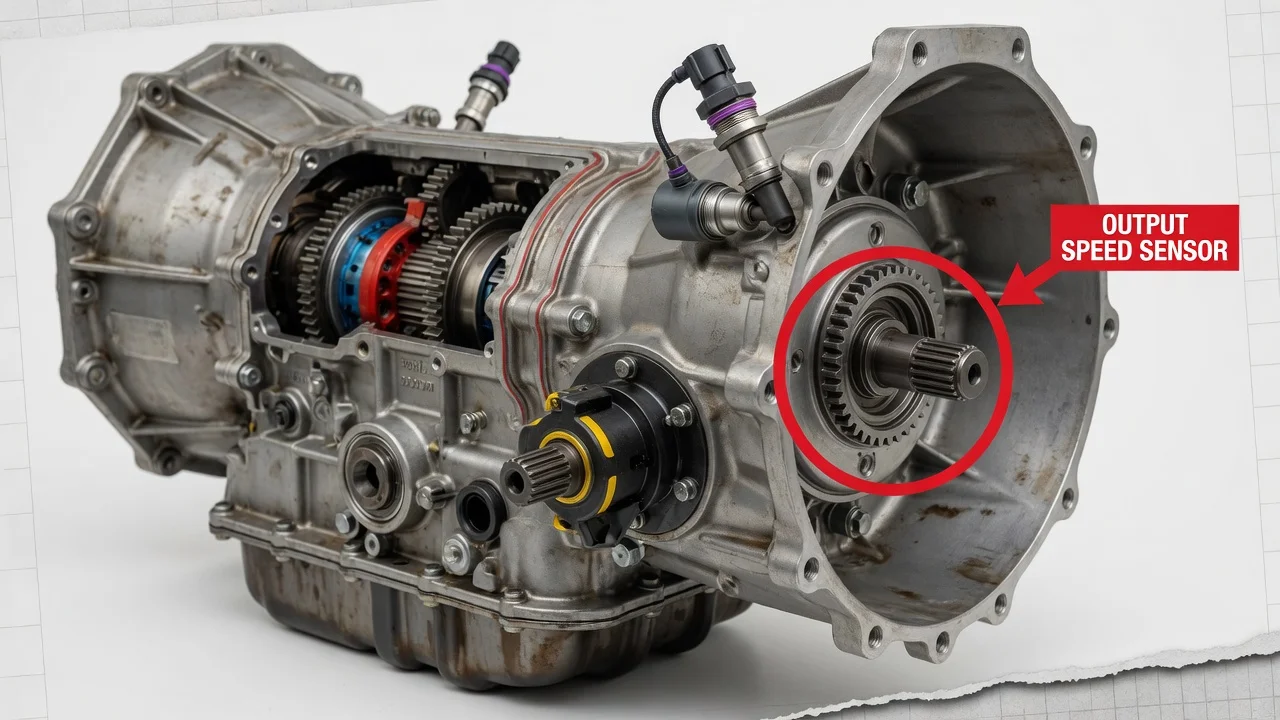
If your scan tool has flagged an output speed signal fault, or the speedometer and shifts have become erratic, finding the sensor is usually the first physical step. Allison builds several transmission families for pickups, motorhomes, buses and medium-duty trucks. The sensor's general position is the same across them, but its exact placement and access differ by series and drivetrain layout. This guide explains where to look, what the sensor does and how to avoid replacing a good part.
Where the output speed sensor is located
On Allison automatics, the output speed sensor is mounted at the rear of the transmission, where it can read the rotation of the output shaft. It fits into the rear housing area so its tip sits close to a toothed or slotted ring that turns with the output. Look at the back end of the case, near where the driveshaft or transfer case attaches, not at the bell housing end where the engine mounts. The sensor is a small cylindrical body held by a single bolt or bracket. It has an electrical connector on top and an O-ring that seals it to the housing.
Allison units commonly have two other speed sensors: one reads engine or input speed and one reads turbine speed. These usually sit further forward on the case. Because all three look similar, confirm which one you have before unplugging or removing anything. Check its position, the harness routing and the service information for your exact model. Which side of the case the output sensor faces, and whether it sits on the main case, an extension housing, a transfer case adapter or a retarder housing, depends on the configuration described below.
How the output speed signal is used
The output speed sensor reports how fast the transmission output shaft is turning. As the toothed ring passes the sensor tip, the sensor produces a pulsing signal that gets faster as road speed rises. The transmission control module compares this signal with engine and turbine speed. From that comparison it determines which gear is actually engaged, calculates clutch slip, times shifts and confirms that each range change happened as commanded.
On many vehicles, the same signal also feeds vehicle speed information to the speedometer, cruise control or other modules, though the signal path varies by vehicle manufacturer. If the output signal drops out, reads erratically or disagrees with the other speed inputs, the control module may set a diagnostic code. It may also switch to a protective mode that holds a fixed gear and limits shifting. That is why a sensor or circuit fault can cause both a driveability complaint and an instrument cluster symptom.
What changes the location and access
The transmission type is the biggest variable. Allison's light-duty 1000 series, used in some full-size pickups and vans, works on the same principle as the medium-duty 2000 and 3000 families and the heavy-duty 4000 family, but their rear housings differ. Generation matters too. Earlier and later versions of the same family can differ in connector style, sensor design and mounting details, so a sensor that looks right may still be the wrong fitment.
Drivetrain layout changes access. On a two-wheel-drive vehicle, the sensor sits at the rear housing near the driveshaft yoke and is often reachable from underneath. On four-wheel-drive versions, the transfer case attaches to the back of the transmission, so the adapter, transfer case, shift linkage or crossmember may crowd the sensor. Units with an integral output retarder have an extra housing at the rear, which changes where the output sensor mounts. Exhaust routing, skid plates and chassis equipment on motorhomes and vocational trucks can also block access. As a result, the same transmission can be easy to reach in one vehicle and awkward in another.
What the owner can do
Start by identifying the transmission. Allison units carry an identification plate on the case with model and serial information. Record it along with the vehicle VIN, because parts and procedures depend on both. Next, read the stored diagnostic codes with a scan tool that can access the transmission control module. Output speed circuit and performance codes point to a problem with the signal, not automatically to a failed sensor. Note any related codes, the freeze-frame data and when the fault appears, such as on cold starts, on rough roads or after recent work.
With the engine off and the vehicle safely supported, inspect the sensor and its harness. Look for a loose or corroded connector, broken locking tabs, chafed wires near the exhaust or crossmember, fluid wicking into the connector and damage from road debris. If you remove a magnetic-type sensor, check the tip for fine metallic debris and note what you find, because it can indicate internal wear. Also check the transmission fluid level and condition using the procedure and fluid specification for your unit. Low or degraded fluid can cause shift behavior that resembles a sensor fault.
If testing points to the sensor, replacement is usually a modest job. Disconnect the connector, remove the retaining bolt, pull the sensor straight out and install the correct part with a new seal. Expect a small amount of fluid loss and top up afterward. Then clear the codes, road test the vehicle and confirm on live data that the output speed reading tracks vehicle speed smoothly.
Limitations and when to get help
A code or symptom pointing to output speed does not prove the sensor has failed. The same complaints can come from wiring faults, a damaged tone ring, the wrong sensor part, a control module or software issue, or a mechanical problem inside the transmission. Some checks, such as measuring sensor resistance or signal output, need the specification and test procedure for your exact unit. These values differ across Allison models.
Use the factory service information for your vehicle and transmission, or see a shop familiar with Allison units, in any of these cases: the code returns after a new sensor, the transmission stays in a protective mode, other speed sensor or clutch codes are present, or reaching the sensor requires removing the transfer case, retarder components or exhaust. Bring the transmission identification, the codes and the service history so the technician can choose the right repair without starting from scratch.