ABS Wheel Speed Sensor Electrical Fault in Circuit: Troubleshooting
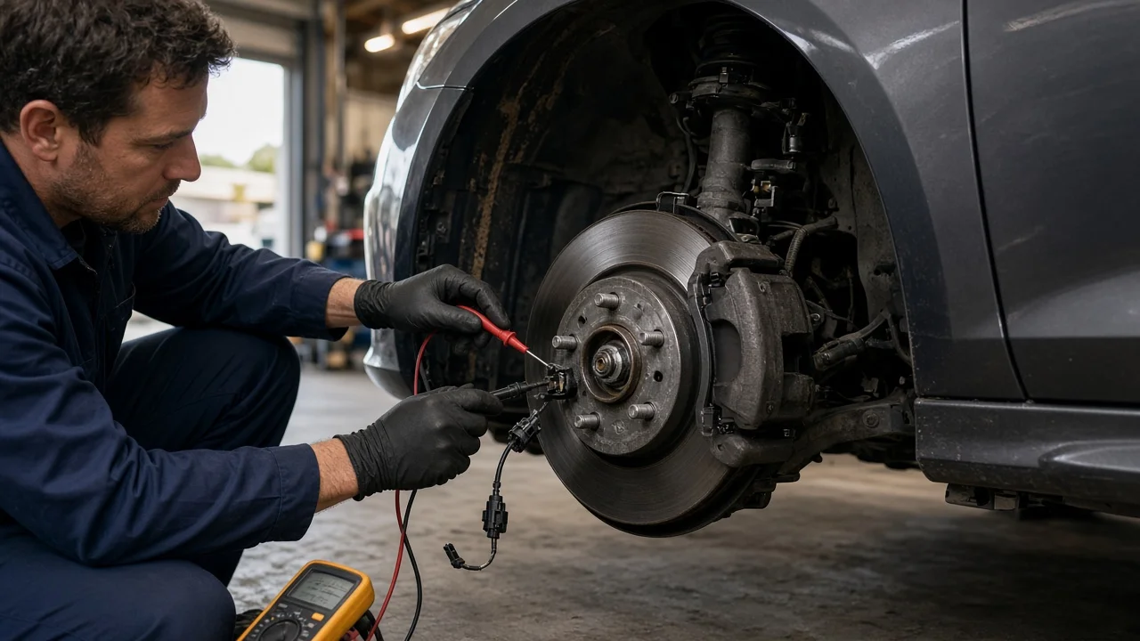
An ABS wheel speed sensor electrical fault in circuit means the ABS control module has seen a signal it cannot accept from one wheel. That can be an open, a short, an out-of-range reading or a signal that drops out. The code points to a circuit, not automatically to a failed sensor. Wiring, connectors, the module's power supply and even low 12-volt system voltage can trigger the same warning, so isolate the fault before you buy parts.
Establish the symptoms
Start by writing down exactly what the vehicle does. Note which lights are on: the ABS light alone, ABS together with traction or stability control, or the red brake warning as well. Record whether the light comes on at startup, only after the vehicle begins moving, or only above a certain speed. A fully open circuit usually trips the warning during the module's self-check or as soon as the wheels turn. A marginal connection often shows up only at speed, over rough pavement or while turning.
Associated signs and recent changes matter just as much. Note whether the speedometer drops out, cruise control stops working, or the ABS pulses during low-speed stops. Then list any recent work or events: brake pads or rotors, hub or wheel bearing replacement, axle or suspension repairs, tire changes, a curb strike, a dead battery or a jump start. A fault that appears right after hub work points toward a damaged connector, a pinched harness, or a bearing installed with its magnetic encoder facing the wrong way. If you have a scan tool, save the exact code description, the wheel it names and any freeze-frame or status data before clearing anything.
Distinguish plausible causes
Harness damage is the most common cause. The sensor lead runs along the knuckle and suspension, where it flexes with every bump and steering movement. A conductor can break inside intact-looking insulation, causing a fault that comes and goes with suspension travel or steering angle. Visible chafing, stretched sections, missing retaining clips or a fault that reacts to bumps all support this cause. Connector problems are a close second: water intrusion, green corrosion, a broken locking tab or a pushed-back terminal. A failed sensor is also common. Passive two-wire sensors can develop an open or shorted coil, and active sensors can lose their internal electronics. The case for the sensor is stronger when its own terminals test bad, and weaker when it tests good at its connector but the signal is lost before the module.
Power and ground problems behave differently. A weak battery, loose or corroded battery terminals, poor charging output or a high-resistance ABS module ground can set codes for several wheels at once, often alongside other module faults. One wheel faulting while the other three read normally weakens this explanation. A damaged or rusted tone ring usually sets a signal or plausibility code rather than an electrical circuit code, although both can appear together. An internal ABS module failure is the least likely cause and should be considered only after the harness, supply and ground have been proven good.
On hybrids and electric vehicles, the wheel speed sensors and ABS module run on the low-voltage system fed by the 12-volt auxiliary battery, not on the high-voltage traction battery. A weak 12-volt battery can still cause these codes. The orange high-voltage cables and components are a separate system, and this diagnosis does not require touching them. Anyone without high-voltage training should stay clear of them.
Checks in a useful order
Begin with safe observations. Park on level ground, switch the vehicle off, set the parking brake and chock the wheels. If you raise the vehicle, support it on proper jack stands. Trace the sensor harness from the sensor to the body connector, looking for rubbing, melted or stretched spots, and broken clips. Unplug the connector and inspect it for corrosion, bent pins and a damaged seal. Check that the battery terminals are clean and tight. Use the wiring diagram to locate the ABS fuses and inspect them. Replace a blown fuse only with the same fuse rating, and find out why it blew before driving.
Tool-based tests come next. A scan tool with live wheel speed data lets you compare all four wheels while rotating the suspect wheel by hand or driving slowly in a safe area. A reading that drops to zero while the others stay steady confirms which circuit is affected. Wiggling the harness and connector while watching live data or circuit status can reveal an intermittent break. With a multimeter and the correct wiring diagram for your exact vehicle, first identify the sensor type. On a passive sensor, compare its resistance with the specification, check each terminal for a short to ground, and look for an AC voltage that rises as the wheel spins. On an active sensor, resistance readings are not a meaningful pass or fail test. Instead, check for supply voltage from the module with the ignition on. For either type, disconnect both ends and test each wire from the sensor connector to the module connector for continuity, then check for shorts to ground and between circuits. Finally, measure voltage drop across the module's power and ground circuits under load.
Some steps are better left to a qualified technician. These include back-probing module connectors without damaging the terminals, viewing the sensor signal on an oscilloscope, running ABS module self-tests, and any relearn or calibration your vehicle needs after a repair.
Interpret the findings
Each result narrows the fault without proving the whole repair. Visible harness damage that matches when the fault occurs strongly supports a wiring repair, but confirm it with a continuity test across the damaged section. A passive sensor that reads open or shorted at its own terminals establishes a sensor failure. If it reads within specification at the sensor but the circuit is open at the module connector, the harness is at fault. If an active sensor has no supply voltage at its connector, check for supply at the module output. Supply present at the module but missing at the sensor points to wiring. Supply missing at the module, despite good module power and ground, makes the module a suspect.
When several wheels set codes together and you found low system voltage or a poor ground, repair that first, clear the codes and retest before touching any sensor. Where left and right sensors are interchangeable, swapping them and seeing whether the fault follows the sensor is useful confirmation. After any repair, clear the codes and road test with live data. A code that returns immediately means the fault has not been fully isolated. An intermittent fault with no visible damage and no failed test is still unconfirmed. Reproduce it before replacing a sensor or module.
Urgency and next action
When only the ABS light is on, the base brakes usually still work, but anti-lock, traction and stability control may be disabled. Wheels can lock under hard braking, and stopping distances may increase on wet or slippery roads, so drive gently and arrange a repair soon. Stop driving and have the vehicle inspected or towed if the red brake warning light is on, the pedal feels soft or sinks, brake fluid is leaking or low, or you notice grinding or pulling. On many vehicles, brake-force distribution also depends on wheel speed signals, which is why the red light can come on with an ABS fault. No fixed distance can be considered safe while a brake warning is active.
For an efficient repair, give the shop the exact codes and the affected wheel, any freeze-frame data, when the fault appears, and any recent work. Include the results of your checks with the readings you took, plus the year, make, model and VIN so the correct sensor and wiring diagram are used. On some vehicles the sensor is built into the hub or bearing assembly. In that case, a confirmed sensor failure means replacing the hub assembly rather than a separate sensor.