700R4 Transmission Speed Sensor Identification
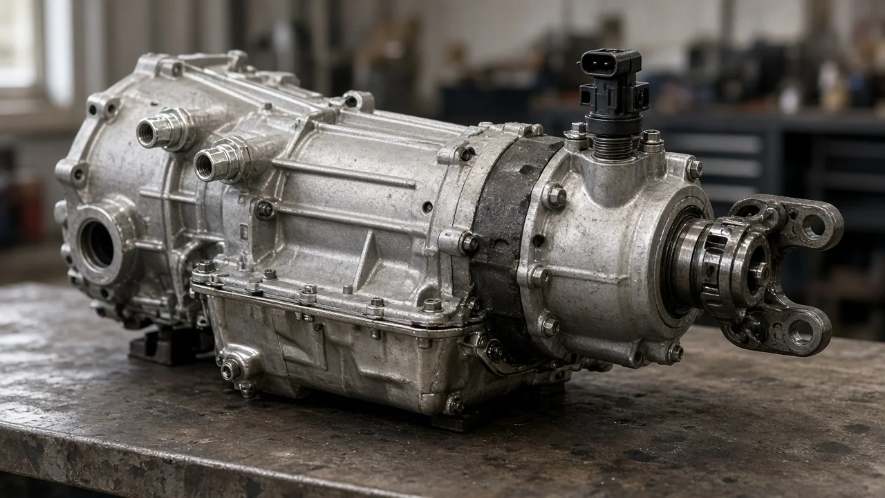
Owners shopping for a 700R4 speed sensor often find that their transmission has no sensor at all, or that the part sits in the tailhousing rather than inside the case. Before you buy parts or chase a speedometer, lockup or cruise control problem, you need to know which speed-signal setup the vehicle uses. This guide explains what to look for, why configurations differ, and why a symptom alone does not prove the sensor has failed.
Short answer: what speed sensor a 700R4 uses
The 700R4 is a hydraulically controlled four-speed automatic that GM used through the 1980s and early 1990s. It was later renamed the 4L60, and the electronically controlled 4L60E came after it. The 700R4 shifts using a governor and a throttle valve cable, so it has no internal input or output speed sensor that commands shifts. When a 700R4-equipped vehicle does have a transmission-mounted speed sensor, it is usually a vehicle speed sensor (VSS) held in the extension housing at the rear of the transmission. It reads a toothed reluctor on the output shaft. Other vehicles use a mechanical speedometer cable driven by a plastic gear in the same area. In some of those, the electronic speed signal comes from the speedometer or a buffer module rather than from the transmission.
Identification therefore comes down to two questions. Is the speed pickup at the tailhousing electronic or mechanical? And is the transmission actually a 700R4, rather than a 4L60E with a similar-looking case and pan?
How the speed signal works on a 700R4
A typical tailhousing VSS is a magnetic pickup. As the reluctor teeth on the output shaft pass the sensor tip, they generate an alternating voltage, and its frequency rises with road speed. The engine computer, or a separate module on some trucks, converts that signal for the speedometer, cruise control and torque converter clutch strategy. On computer-controlled engines, the ECM combines vehicle speed with other inputs to decide when to apply the lockup clutch through a solenoid on the valve body.
With a mechanical drive, a gear on the output shaft turns a driven gear in a sleeve at the tailhousing, and the cable carries that rotation to the gauge. Driven gears come in different tooth counts to match axle ratio and tire size. Shift points come from governor pressure and throttle valve pressure. For that reason, a dead speed sensor on a 700R4 does not normally change upshift timing directly, but it can affect lockup and anything else that relies on the speed signal.
What changes the answer
The speed-sensing hardware depends on the vehicle the transmission came from, not only on the transmission type. Carbureted cars and early trucks commonly use a cable. Many later fuel-injected trucks and some cars use a tailhousing VSS. Some cars kept a cable to the gauge and generated the computer's speed signal inside the instrument cluster. In that case the transmission carries no sensor, even though the ECM still reads vehicle speed.
Fitment also varies with the hardware. Extension housings differ between two-wheel-drive and four-wheel-drive versions, and between mechanical and electronic speedometer provisions. A four-wheel-drive vehicle may pick up speed at the transfer case instead. Swapped or rebuilt transmissions add more uncertainty. A previous owner may have changed the tailhousing, added an aftermarket sensor or adapter for a digital gauge or fuel injection system, or installed a 4L60E. On a 4L60E, the tailhousing speed sensor feeds the shift strategy, so a fault there can change shift behavior in ways a 700R4 would not.
How to identify yours and what to check
Start by confirming the transmission type. A 700R4 has a throttle valve cable running from the carburetor or throttle body to the transmission, and no multi-pin connector for shift solenoids. A 4L60E has no throttle valve cable and has an electrical connector on the side of the case for its solenoids. If the identification tag or stamped code on the case is legible, it can confirm the unit.
Next, look at the rear of the extension housing. A cable with a threaded or clipped fitting indicates a mechanical drive. A sensor with a wiring harness, typically a two-wire connector held by a bolt or retainer, indicates a VSS. If you find only a cable, check the cluster wiring or the service information for where the speed signal originates before ordering a transmission-mounted sensor. Note the housing shape, the drive configuration and any service history showing a swap. Bring those details, or the old part, when you match a replacement.
Common symptoms include a dead or erratic speedometer, cruise control that will not engage, or a converter that never locks up. For any of these, read stored diagnostic codes first. Many GM OBD-I systems use code 24 for a vehicle speed sensor circuit fault, but confirm the meaning for your exact engine and computer. A code points to a circuit that includes the wiring, connector, reluctor, gauge and module, not only the sensor. Check the connector for corrosion and damaged wires, and inspect the sensor tip for metal debris, which can weaken the signal. Testing sensor resistance or AC output requires the specification for that vehicle, so do not assume one value fits every application. Removing the sensor can release some fluid; top up with the fluid specification listed for the vehicle.
Limitations and next step
A symptom alone does not confirm a failed speed sensor. A mechanical speedometer can fail from a stripped driven gear or a broken cable. An electronic one can fail from wiring, a cluster fault or a module. Lockup problems can come from the converter clutch solenoid, the brake switch, other engine inputs or hydraulic issues. Wiring colors, connector locations, test values and code definitions vary by model and year. Use the factory service information for the exact vehicle, identified by its VIN, before you replace parts.
Professional help makes sense if the transmission has been swapped, the wiring altered, or the speed reading needs recalibration for different gearing or tires. A transmission shop or an electrical diagnostic specialist can confirm the configuration and test the circuit with the right equipment. Repair options range from a connector repair or new sensor to recalibration or a corrected driven gear. The right choice depends on what the testing actually shows.