7.3 IDI Glow Plug Relay Wiring Diagram: Circuit Layout, Testing and Safe Isolation
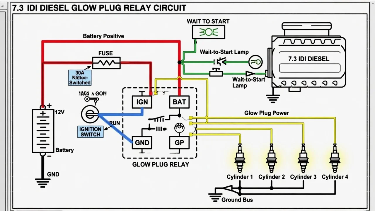
Hard starting on a cold 7.3 IDI usually points to the glow plug circuit, and the relay sits at the center of it. This guide covers the wiring layout: which terminals connect where, how current reaches the eight glow plugs, what differs between controller versions and manual conversions, and how to test the circuit safely. Treat it as a map for understanding your truck, then confirm the details against the factory wiring diagram for your exact year.
The short answer: how the relay is wired
On most 7.3 IDI trucks, the glow plug relay is a combined relay and timing controller mounted near the rear of the engine on the driver side. It has two large studs and a small connector. One large stud is the battery feed. It typically comes from the battery side of the starter relay through a fusible link, so it is live at all times, even with the key off. The other large stud is the output, which feeds the glow plug harness. That harness splits to the two banks of four plugs, one wire per plug.
The small connector carries the control and indicator wiring. It includes an ignition run feed that wakes the controller when the key is turned on, and an output that drives the wait-to-start lamp on the dash. The ground path runs either through the controller housing and its mounting or through a dedicated wire, depending on the version. Wire colors and pin positions vary by year and harness revision, so use the diagram for your model year rather than a generic sketch.
How the circuit works
When the key reaches run, the controller receives ignition voltage. It closes its internal high-current contacts, connecting the battery feed to the glow plug output. The plugs heat the precombustion chambers so the fuel can ignite at cranking speed. At the same moment the controller lights the wait-to-start lamp. The lamp time is not necessarily the same as the plug-on time, so the plugs may keep heating after the lamp goes out.
The controller decides how long to energize the plugs based on engine temperature. A cold engine gets a longer cycle and a warm engine gets a short one or none. Exact timing depends on the controller version. Because eight plugs draw a large combined current, far more than ordinary relays or switches can handle, the main contacts and the feed wiring carry serious load during every cold start. That load is why burned contacts, corroded studs and failed fusible links are common faults.
What changes the wiring
The earlier 6.9 IDI and some early systems used a separate relay and control module instead of one combined unit. Their diagrams look different, even though the high-current path from battery to plugs is similar. Replacement controllers from different suppliers may also change the small-connector layout. Before you buy a part or splice wires, check that the replacement matches your harness.
Glow plug voltage rating must match the controller strategy. Plugs designed for one system can overheat on another. Overheated IDI plugs are known to swell at the tip and break off into the precombustion chamber, which can cause engine damage. Check the markings on the plugs and the controller, and replace them as a matched set.
Many owners convert to a manual setup: a continuous-duty solenoid, a momentary dash switch and a fused trigger circuit. In that layout the fuse rating protects only the switch and solenoid coil circuit, while the plug current still flows through the solenoid and the fusible link. A manual system removes temperature-based timing. Holding the button too long is a direct path to swollen plug tips. Most of these trucks use two batteries in parallel, and the 7.3 IDI is a conventional 12-volt diesel with no high-voltage traction system. The battery feed still carries enough current to cause severe burns or melt a tool shorted across it.
Safe isolation before you work on it
Because the battery-feed stud is always hot, disconnect the negative cables from both batteries before removing nuts from the relay studs or unplugging the glow plug harness. Disconnecting only one battery leaves the circuit live through the other. Keep the removed cables away from the battery terminals. Remove rings and metal watchbands, and use insulated tools around the large studs. Reconnect the batteries only after every stud nut is tight and every plug connector is seated.
Testing the relay and glow plug circuit
Start with the batteries, since weak cells make every glow plug fault look worse. Check resting system voltage at each battery, clean the battery terminals, and confirm charging output with the engine running. With the engine cold, connect a voltmeter or test light to the output stud and turn the key to run. You should see near battery voltage for the glow cycle, then the output should switch off. Next, measure voltage drop across the two large studs while the relay is energized. A healthy relay shows only a few tenths of a volt at most. A larger drop points to burned internal contacts or corroded connections.
To check the plugs, isolate the batteries, unplug each glow plug connector and measure resistance from the plug terminal to engine ground. Good plugs give a low reading similar to one another. An open reading means a burned-out plug. An inductive clamp meter on each plug wire during the glow cycle is another way to compare the plugs. A plug drawing noticeably less current than the rest is suspect.
If the output stays live long after the cycle should end, or stays live with the key off, the contacts may have welded closed. That fault shows up as an unexplained parasitic draw and dead batteries. It also cooks the plugs, so stop using the truck and disconnect the batteries until the relay is replaced.
Limitations and next step
Controller versions, harness revisions and previous owner modifications mean no single generic layout fits every truck. Confirm wire colors, terminal positions and fusible link locations with the factory wiring diagram for your model year before splicing or replacing parts. If testing shows a broken plug tip, repeated fusible link failure, melted harness insulation or a no-start you cannot trace with these checks, have a diesel technician inspect the engine. Removing broken plug tips and repairing damaged high-current wiring both call for experience and the right tools.