6R80 Valve Body Diagram and Component Identification
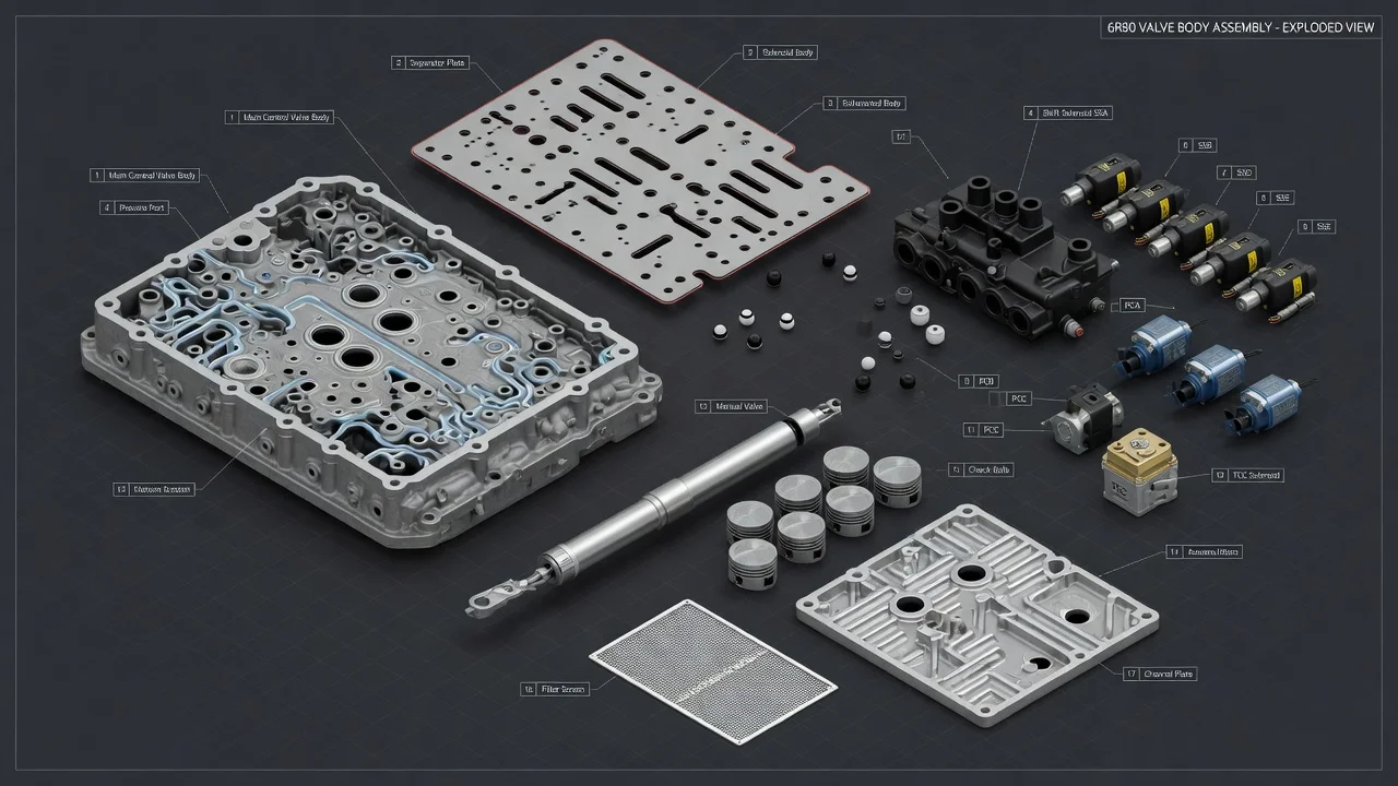
The 6R80 is Ford's six-speed rear-wheel-drive automatic, used in the F-150, Expedition, Mustang and several other Ford and Lincoln models. Its valve body is the hydraulic control center bolted to the bottom of the case, working together with an electrical solenoid body. This guide explains what a 6R80 valve body diagram shows, how to identify the main parts, what differs between versions, and how to use that knowledge without mistaking a symptom for a confirmed failed component.
What a 6R80 valve body diagram shows
A typical 6R80 transmission valve body diagram shows two assemblies stacked together. The first is the hydraulic valve body itself: upper and lower castings machined with bores that hold spool valves, springs, retainers and check balls. A separator plate with gaskets sits between the castings and routes fluid through precisely sized holes. The second is the solenoid body, a module that bolts to the valve body and carries the electrical control parts. When you identify components, it helps to sort them into three groups: castings and separator plate, valves and springs in their bores, and the solenoid body with its solenoids and sensors.
Exploded views in factory service information and in rebuild kit instructions number each valve, spring and retainer by bore so they can be reinstalled in the correct order and orientation. The names used for the same part can differ between sources, so match components by their position in the casting and their shape rather than by name alone. A diagram is a map for assembly and identification; it cannot show wear inside a bore or whether a solenoid is working correctly.
Main components and how to identify them
The manual valve is usually the easiest part to recognize. It connects to the shift selector through the internal detent lever and moves with each gear range, directing fluid to the circuits for park, reverse, neutral and drive. Near it you will find the main pressure regulator valve and related valves that set line pressure, the base pressure the rest of the system works from. Several clutch regulator valves control the apply pressure for the individual clutch packs, and a separate set of valves handles torque converter clutch apply and release. Check balls sit in specific pockets in the casting; the diagram marks each location, and they are easy to lose or misplace during disassembly.
The solenoid body carries the shift solenoids, normally identified by letter, along with a torque converter clutch solenoid and a line pressure control solenoid. Depending on model year, the same assembly may also include the turbine shaft speed sensor, the output shaft speed sensor, the transmission fluid temperature sensor and the transmission range sensing function. Each solenoid body is supplied with characterization data, often shown as a code on its label, that the control module uses to compensate for small manufacturing differences between solenoids.
How the valve body controls shifts
The transmission pump supplies fluid under pressure, and the regulator valves trim it to a controlled line pressure. The manual valve then sends that pressure to the circuits allowed by the selected range. Within drive, the powertrain control module decides when to shift based on vehicle speed, throttle position, engine load and fluid temperature, and it commands the solenoids electrically. The solenoids produce control signals that move the clutch regulator valves, and those valves feed or release pressure to the clutch packs inside the transmission.
Like many modern automatics, the 6R80 performs clutch-to-clutch shifts: one clutch releases while another applies, and the timing between them determines whether a shift feels smooth, harsh or slips. That is why shift behavior depends on both the electrical side, meaning commands, solenoid performance and adaptive learning, and the hydraulic side, meaning fluid condition, valve movement and how well each bore holds pressure. A fault in either area can produce similar symptoms.
What changes the answer
The 6R80 was revised over its production run, and valve body castings, separator plates, solenoid bodies and calibrations are not identical across all years and applications. A truck, a Mustang and an Expedition can use different parts and different software even though the transmission type is the same. The 6R80 also shares its basic architecture with the ZF 6HP26 and with Ford's lighter-duty 6R60, but shared design does not mean parts interchange. Versions built for markets outside the United States can differ again. Fitment should always be confirmed by part number and vehicle identification number rather than by appearance or by the transmission name alone.
Service history also changes what you are likely to find. A unit with a previously replaced solenoid body, a remanufactured valve body or updated software may not match an original diagram exactly. Operating conditions matter too: fluid temperature, fluid age and towing or high-load use all affect how the hydraulic system behaves and how the control module adapts its shift timing.
What the owner can do
Start by describing the problem precisely. Note which shift is affected, whether it happens cold or warm, at light or heavy throttle, during upshifts or downshifts, and whether it is constant or intermittent. Then read diagnostic codes with a scan tool that can access transmission data, not only generic engine codes. Transmission faults generally appear in the P07xx range, and the code description, freeze frame data and live readings such as solenoid commands, speed sensor values and fluid temperature narrow the possibilities far more than the symptom alone.
Check fluid level and condition using the procedure for your vehicle. Many 6R80 applications have no conventional dipstick, so the level is checked at a plug with the engine running and the fluid within a specified temperature range. The fluid specification commonly listed for this transmission is Mercon LV, but confirm it in the owner's manual or service information. Burnt odor, dark color or debris is worth recording before any further work.
Gather the service history, including fluid changes, earlier transmission repairs and any software updates. If parts are being considered, have them matched to the vehicle by identification number. Replacing a solenoid body typically requires loading its characterization data into the control module with a capable scan tool, and an adaptive relearn may be needed afterward; skipping these steps can leave shift quality poor even with a new part installed.
Limitations and next step
A diagram helps you understand and identify parts, but it does not diagnose the transmission. A harsh or slipping shift can come from low or degraded fluid, outdated software, a weak solenoid, wear in a valve bore, worn clutch packs or even an engine torque issue, and a code that points to a circuit does not prove which component inside it has failed. Pinpointing the cause usually requires scan data, electrical testing and sometimes hydraulic pressure testing.
Repair options range from a fluid service or software update to solenoid body replacement, valve body repair or replacement, or a full overhaul when internal clutches are damaged. Once diagnosis points inside the transmission, or when programming and relearn procedures are required, a transmission specialist with the correct service information and scan equipment is the practical next step. If the vehicle slips badly, will not engage a gear or shows a warning, limit driving until it has been inspected to avoid further internal damage.