6R80 Transmission Output Speed Sensor Location
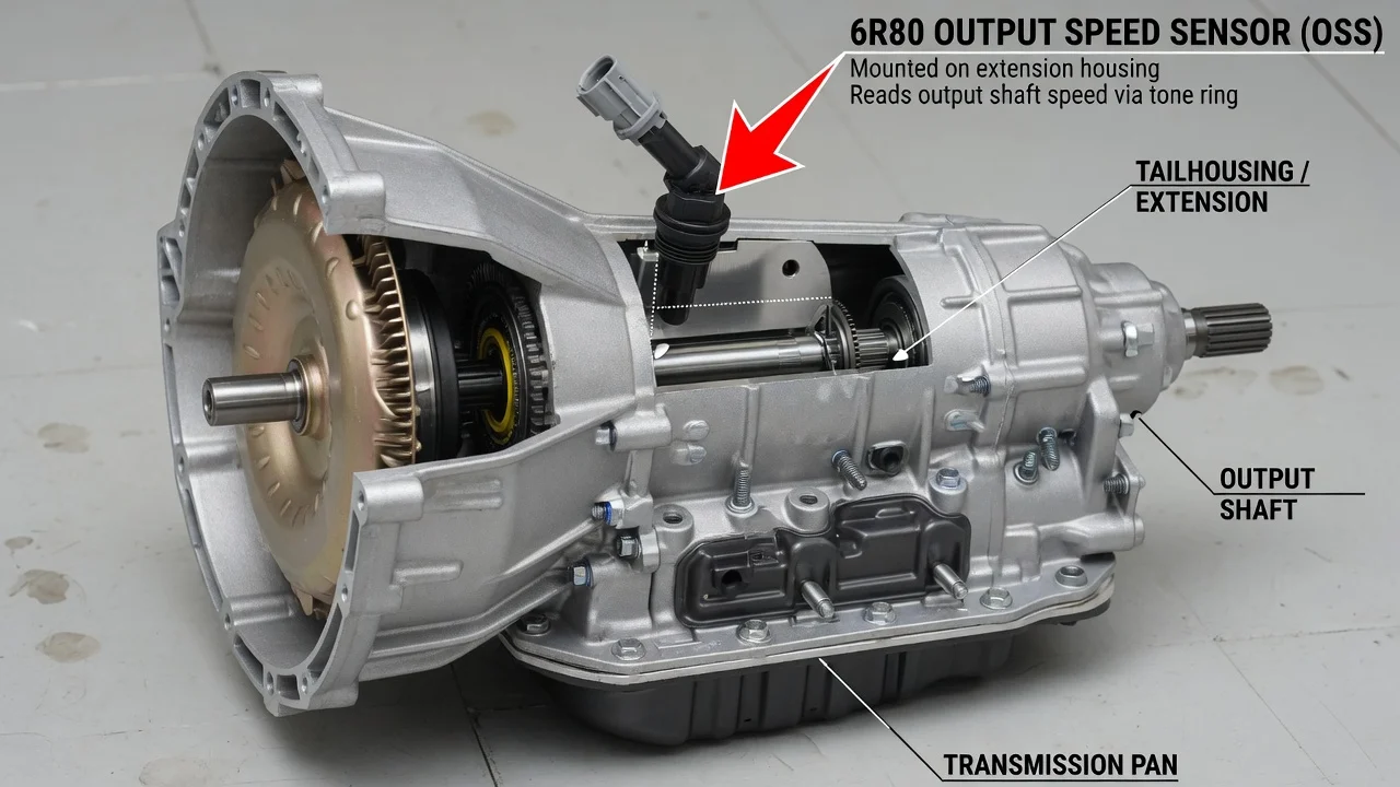
On the Ford 6R80 six-speed automatic, you cannot reach the output shaft speed sensor from under the vehicle. It sits inside the transmission, above the oil pan, as part of the internal wiring harness that technicians usually call the lead frame. That placement shapes how the sensor is diagnosed, how it is replaced and what the job involves. This guide covers where the sensor sits, how it works, and what to check before you decide it has failed.
Where the 6R80 Output Speed Sensor Sits
The output shaft speed (OSS) sensor on the 6R80 is mounted internally, in the valve body area toward the rear of the case, behind the oil pan. It is integrated into the internal harness assembly, or lead frame. That assembly typically also carries the turbine shaft speed sensor and the transmission fluid temperature sensor, and it routes their signals to a single pass-through connector on the transmission case. The external connector is the only part of this circuit you can see without opening the transmission.
Reaching the sensor generally requires draining the fluid and removing the pan and filter. In most cases you also have to remove the valve body to free the harness. On most applications the transmission can stay in the vehicle. The sensor is normally serviced together with the harness, so parts catalogs often list the replacement as an internal harness or lead frame assembly rather than a standalone speed sensor. Confirm the exact part for your vehicle with a VIN-based lookup before ordering.
How the Output Speed Sensor Works
The OSS is a magnetic pickup positioned next to a toothed target on a rotating member tied to the output side of the gearset. As the teeth pass the sensor tip, it produces a signal whose frequency rises and falls with output shaft speed. The control module compares this reading with turbine shaft speed to calculate the actual gear ratio and confirm that each shift has completed. It also uses the comparison to schedule shifts and manage torque converter clutch apply. On many vehicles the output speed signal also feeds the speedometer or other modules, although the exact signal path depends on the application.
When the signal drops out or does not make sense, the module stores diagnostic codes and may switch to a fail-safe strategy. Fail-safe can mean limited gears, firm or delayed shifts, and a warning light. The magnetic tip also attracts fine metal particles suspended in the fluid. Heavy wear material can therefore interfere with the signal, so fluid condition and service history matter when interpreting a speed sensor fault.
What Changes the Answer
First confirm that the vehicle actually has a 6R80. This transmission was used in many model years of the F-150, Expedition and Navigator from roughly 2009 through 2017, and in the Mustang from 2011 through 2017. Ford also built related six-speed units, such as the lighter 6R60 and the heavier-duty 6R100 and 6R140, and those differ in components and service details. The 10-speed 10R80, which replaced the 6R80 in several of these vehicles, is a different design, so 6R80 instructions do not apply to it. To confirm the transmission type, check the identification label on the case, the vehicle build data, or a dealer VIN lookup.
Drivetrain layout changes the work around the transmission, not the sensor location. On four-wheel-drive versions, the sensor still sits inside the main case, but exhaust routing, crossmembers and the transfer case can affect pan access and working room. The internal harness was also revised during production, so part numbers can differ by model year, engine and application. Fitment should be checked against your specific VIN rather than the transmission name alone.
What the Owner Can Do
Start by reading the diagnostic codes with a scan tool that can access transmission data, not just engine codes. Generic output speed sensor circuit codes fall in the P0720 to P0723 range, and turbine speed codes in the P0715 to P0718 range. If the tool shows live data, watch the output shaft speed reading against vehicle speed during a road test. A reading that drops to zero, jumps or disagrees with actual speed is useful evidence. Keep in mind that a code identifies a circuit or signal problem, not necessarily a failed sensor.
Several checks should come before opening the transmission. Verify the fluid level using the correct procedure: many 6R80 applications have no conventional dipstick and use a level check plug with a specified fluid temperature range. The fluid specification is Mercon LV. Inspect the external connector and nearby wiring for damage, corrosion, chafing or fluid wicking. Note whether other modules have stored speed-related codes, since problems shared across several systems, such as ABS wheel speed faults, can point away from the transmission. Write down when the symptoms appear, including temperature, gear and speed, because shift behavior patterns help separate electrical faults from mechanical ones.
If testing points to the internal circuit, the usual repair is replacing the lead frame. That job includes a new filter and pan gasket, the correct fluid, and the proper fill and level check procedure afterward. Clearing adaptive shift data or running a relearn is commonly recommended once the work is done. If any valve body or solenoid components are replaced as well, some carry calibration data that must be programmed into the control module. A careful owner with service information, torque specifications and a clean workspace can do this work, but it is more involved than a typical external sensor swap.
Limitations and Next Step
Symptoms alone cannot confirm a failed output speed sensor. Clutch wear, solenoid faults, valve body problems, wiring faults and control module software can all produce similar shift complaints or speed readings. Valve body bolt locations, torque values and fill procedures vary by application, so follow vehicle-specific service information rather than general descriptions. A transmission specialist is the better choice in several situations: the fluid is dark, smells burnt or carries heavy debris; codes return after the harness has been replaced; or you do not have a scan tool that reads transmission data. For a practical next step, record the codes and freeze frame data along with the driving conditions when the fault appears, then share them with whoever performs the diagnosis.