4L60E Transmission Speed Sensor Identification
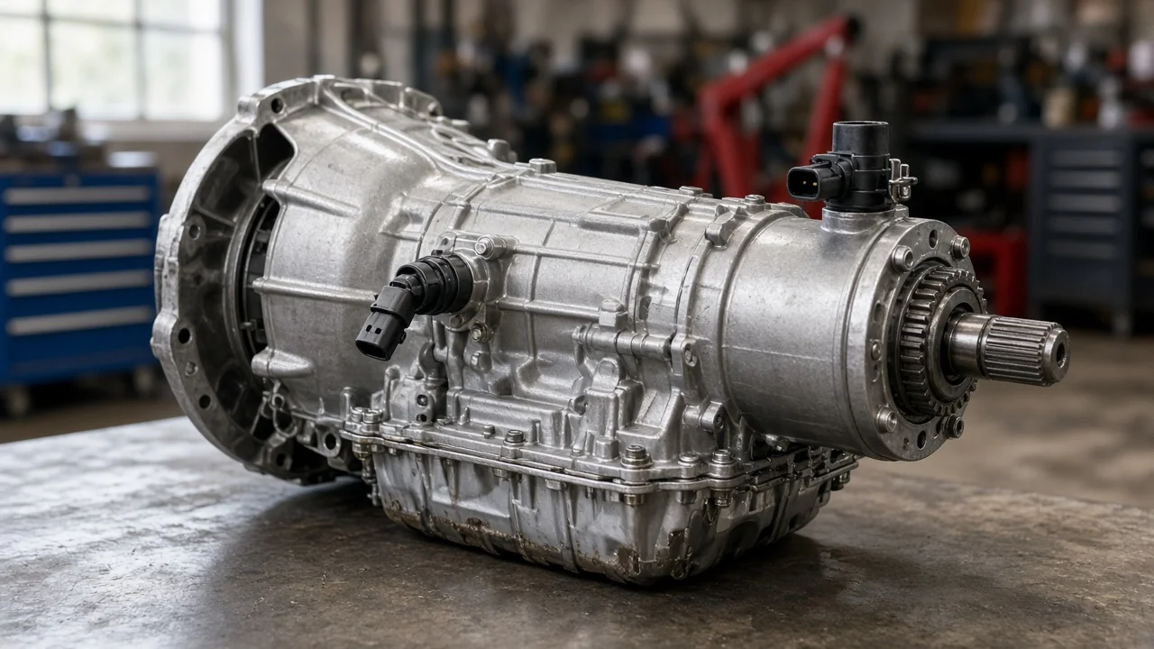
The 4L60E is GM's electronically controlled four-speed automatic, used for years in rear-wheel-drive and four-wheel-drive trucks, SUVs, vans and some cars. Its computer depends on a speed signal to choose shift points, apply the torque converter clutch and often drive the speedometer. Identifying which sensor your vehicle uses, where it is mounted and whether it is actually faulty takes more than matching a symptom to a part. This guide covers identification, operation and a sensible diagnostic path.
Which speed sensor a 4L60E uses
On most 4L60E applications the key sensor is the output speed sensor, often called the vehicle speed sensor or VSS. It is a two-wire magnetic pickup that reads the rotation of the output side of the drivetrain. On two-wheel-drive vehicles it threads or bolts into the extension housing, the tailhousing at the rear of the transmission, and is held in place with a bracket and sealed with an O-ring. On most four-wheel-drive versions the transmission bolts to a transfer case through an adapter, and the output speed sensor is mounted on the transfer case instead of the transmission itself.
Most 4L60E units do not have a separate input speed sensor. Some later applications, and the closely related heavier-duty 4L65E and 4L70E, add one, so do not assume your unit matches a generic diagram. Start by confirming the transmission type. On many GM vehicles the Service Parts Identification label, often found in the glove box or on a door pillar, lists RPO codes; M30 indicates a 4L60E. The identification tag or stamping on the transmission case gives further detail on the specific build.
How the speed signal works
The sensor contains a permanent magnet wrapped in a coil. A toothed reluctor ring turns past its tip with the output shaft or the transfer case output. Each tooth disturbs the magnetic field and induces a small alternating voltage in the coil. As road speed rises, both the frequency and the strength of that signal increase. The powertrain control module, or a separate transmission controller on some vehicles, counts the pulses and converts them into vehicle speed.
The computer combines that speed value with throttle position, engine load and other inputs to decide when to upshift and downshift, how much line pressure to command and when to engage torque converter clutch lockup. If the signal drops out or becomes erratic, shift behavior can become harsh, delayed or confused, and the speedometer and cruise control may stop working. On some older trucks the signal passes through a separate buffer or adapter module before reaching the instrument cluster, and some vehicles also use wheel speed information from the anti-lock brake system, which adds other parts to the circuit.
What changes the answer for your vehicle
Drivetrain layout is the biggest variable. A two-wheel-drive truck, a four-wheel-drive truck and an all-wheel-drive van can place the sensor in different housings, use different sensor lengths and different connectors. Model year matters too, because GM revised connectors, controllers and sensor designs over the production run. Fitment should therefore be confirmed by VIN, RPO codes and drivetrain, not by transmission name alone.
Modified vehicles need extra care. A 4L60E swapped into an older chassis may use a different extension housing, a different reluctor ring or a standalone controller, and its speed signal depends on how that controller was set up. Changes in tire size or axle ratio make the reported speed inaccurate even when the sensor works perfectly; that calls for recalibration, not a new part. Prior transmission rebuilds or transfer case replacement in the service history can also mean the installed parts differ from the original specification.
What the owner can check
Start by recording what happens and when. Note whether the speedometer drops to zero, needles erratically or works only at certain speeds, and whether shift behavior changes at the same moment, such as staying in one gear, flaring between gears, shifting harshly or losing converter lockup. Read the stored diagnostic codes with a scan tool and save any freeze frame data. Codes related to vehicle speed or output speed circuits point toward the signal path, but they describe a circuit condition rather than naming a failed component. If your scan tool shows live data, compare the reported vehicle speed with an independent reference such as a phone GPS during a safe drive.
Next, inspect the wiring and connector. Look for corrosion, a loose or broken lock tab, oil intrusion and harness damage, especially where wires pass near the exhaust or along the frame. With the sensor removed, examine the magnetic tip. A light film of fine particles is common, but heavy metallic debris or chunks can mask the signal and may indicate internal wear that deserves further attention. Check the O-ring for damage, since a leak here can lower fluid level. A multimeter can measure coil resistance and AC voltage output while the wheels are rotated safely on a lift, but results should be compared with the specification for your exact vehicle rather than a generic number.
Check transmission fluid level and condition using the procedure and fluid specification listed for your vehicle, because low or burnt fluid causes shift complaints that can be mistaken for a sensor problem. If replacement is justified, order by VIN and drivetrain to ensure correct fitment, reinstall with a new O-ring, clear codes and confirm the repair with a road test and live data.
Limitations and when to get help
Symptoms associated with a bad speed sensor overlap with damaged wiring, a failing controller or cluster, anti-lock brake system faults, incorrect programming and internal mechanical failures such as worn clutches or a damaged reluctor ring. A new sensor will not fix those, and erratic shifting with slipping or unusual noises points beyond the sensor. Codes that return after replacement, a sensor that tests within specification, or significant debris in the fluid are signs that further diagnosis is needed.
Because sensor location, connector style and test values vary by year and configuration, use the factory service information for your vehicle when possible. If the cause is not clear after the basic checks, a transmission specialist can perform pinpoint circuit tests, review live data and recommend appropriate repair options, from a wiring repair or recalibration to sensor replacement or internal transmission work.