How to Read a 2001 GMC Sonoma Brake Line Diagram
The short answer
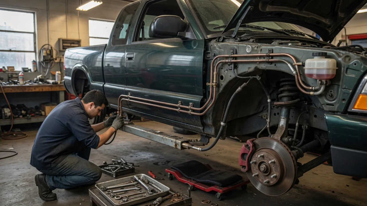
A brake line diagram for a 2001 GMC Sonoma is a routing map. It shows how brake fluid travels from the master cylinder, through any valves or ABS hardware, along the frame, and out to each wheel. To read one, start at the master cylinder and follow each outlet line in turn until it ends at a front caliper or the rear axle. Note every component, fitting and change from rigid steel tubing to flexible rubber hose along the way.
One qualification matters before you rely on any diagram: it must match your exact truck. The 2001 Sonoma was sold in several configurations. These include different cab styles, bed lengths, wheelbases and two- or four-wheel drive. Line lengths, hose part numbers and routing details can differ between them. Confirm that a diagram covers your configuration before you use it to order parts or bend replacement lines.
What the diagram is showing you
Most brake line diagrams, whether from a factory service manual or an aftermarket repair guide, share the same basic elements. Knowing what each one represents makes the drawing much easier to follow.
Master cylinder: the reservoir and pump unit on the driver's side of the engine bay, operated by the brake pedal. Every line on the diagram traces back to it. Hydraulic control components: any valve, junction block or ABS modulator between the master cylinder and the wheels. These usually appear as labeled boxes or outlines with several line connections. Rigid brake lines: steel tubing, normally drawn as solid lines running along the frame or body. Flexible brake hoses: short rubber hoses that let the wheels and axle move. They usually sit at each front wheel and between the frame and rear axle. Fittings and junctions: the points where lines join, split or connect to components, often shown as small circles, nuts or callout numbers. Retainers and clips: the brackets that hold lines to the frame, usually marked with callouts. Their positions define the correct routing. Wheel-end labels: abbreviations such as LF, RF, LR and RR (left front, right front, left rear, right rear) that identify where each line ends.
How to trace the circuits step by step
1) Identify the master cylinder outlets on the diagram and note which line leaves each port. 2) Follow each line to the first component it reaches, and note the component's label. 3) Track every line that leaves that component, and record which wheel or axle each one serves. 4) Mark where each steel line meets a flexible hose. Hoses wear out and are replaced separately from steel lines. 5) On the rear circuit, find where the line meets the axle. Then follow it to the point where it branches toward the left and right wheels. 6) Note each clip and retainer callout along the frame. A replacement line should follow the same path and be secured at the same points. 7) Check the legend or parts list for any numbered callouts, which may give part numbers, line descriptions or fitting types.
Details to confirm for your specific truck
No verified specifications were available for this article. It therefore does not state line lengths, tube diameters, fitting thread sizes, torque values or the exact layout of the 2001 Sonoma's ABS and valve hardware. Do not assume these from a general diagram. Take them from a factory service manual or a parts catalog that lets you filter by model year, drivetrain, cab style and wheelbase.
Drivetrain: two-wheel-drive and four-wheel-drive versions may use different front hoses and routing near the front suspension. Cab and bed configuration: wheelbase changes the length of the line that runs back to the rear axle. Brake hardware: confirm whether your truck has rear drums or rear discs, and which ABS equipment is fitted. The diagram should match what is actually on the vehicle. Prior repairs: older trucks often have spliced or rerouted lines. If your truck does not match the diagram, the diagram may still be right. Check before assuming either is correct.
Practical next step
Compare the diagram with the truck itself. Start at the master cylinder, then trace each line on the vehicle while following it on the drawing. If the routing, components and wheel-end connections all match, you can use the diagram for planning repairs. If anything differs, find the configuration-specific factory documentation before you buy lines or make changes.
Brakes are safety-critical. After any brake line work, the system needs a correct bleeding procedure and a check for leaks. Trucks with ABS may need a specific procedure for this. If you are unsure of any step, have a qualified technician inspect the work before driving.